36 Rockwell Automation Publication 20B-IN017B-EN-P - September 2011
Chapter 3 Component Replacement Procedures
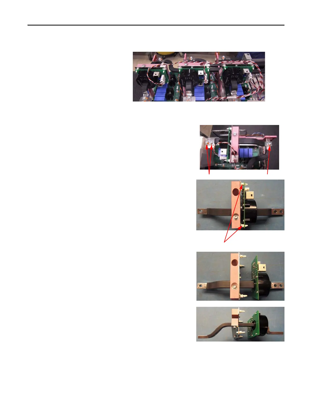
3. Locate the Current Transducer to be replaced.
4. Disconnect the wiring harness from the transducer board. Clip the wire
tie and remove the wiring harness.
5. Remove the three button
head screws that secure the
bus bar. Move the bus bar
and transducer to an ESD-
safe flat surface for working
with it.
6. Using your fingers or
needle-nose pliers, squeeze
the wings of each of the
four spacers and separate
the transducer and board
from the mounting clamp.
7. Loosen the two screws that
hold the two sections of the
CT mounting clamp, but
do not take the screws
completely out. Only
loosen them so that the end
is flush with the bottom of
the CT mounting clamp.
8. Remove mounting clamp
from the bus bar by sliding
the gentle bend of the bus
bar (the end with only one
screw hole) through the
assembly, taking care not to
damage the transducer or the insulation on the bus bar.
W Phase V Phase U Phase
Spacers

 Loading...


