Rockwell Automation Publication 20B-IN017B-EN-P - September 2011 45
Component Replacement Procedures Chapter 3
13. Torque the left screws for each Current Transducer to 5.9 N•m (52
lb•in)
14. Set each Motor Bus Bar in final position and torque the remaining
Current Transducer screw to 5.9 N•m (52 lb•in)
15. Torque each Motor Bus Bar mounting screw (at the bottom) to 9.0 N•m
(80 lb•in)
16. Reassemble remaining components in reverse order.
17. Replace all safety shields and enclosure covers before applying power to
the drive.
Main Control Panel Thermal
Sensor
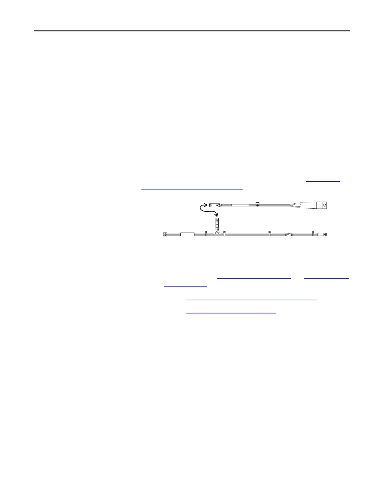
The Main Control Panel Thermal Sensor is located at the upper left of the Main
Control Panel Assembly and is connected to the Heatsink Thermal Sensor by the
Monitor Wire. Refer to the diagram below and to the figures in Component
Diagrams and Torque Specs on page 13 for these instructions.
Remove Components
1. Read and follow the Safety Precautions on page 9 and Important Initial
Steps on page 11.
2. Perform Remove Main Control Panel Assembly on page 21
.
3. Perform Remove Stacking Panel on page 22
.
4. Unscrew one end of the sensor from the Stacking Panel.
Note: This screw and nut are small. Take care that they do not drop.
5. Disconnect the other end from the Monitor Wire.
Install Components
1. Apply thermal grease to the metal side of the new Main Control Panel
Thermal Sensor and install it with supplied screw with star washer
toward the panel. Torque screw to 1.7 N•m (
15 lb•in)
2. Reconnect the Monitor Wire.
3. Reinstall the Main Control Panel Assembly.
4. Replace all safety shields and enclosure covers before applying power to
the drive.
ain
ontro
ane
erma
ensor
Monitor Wire
To
Stacking
Panel
To
Heatsink
Thermal
Sensor
To Power
Interface
Board

 Loading...


