56 Rockwell Automation Publication 20B-IN017B-EN-P - September 2011
Chapter 3 Component Replacement Procedures
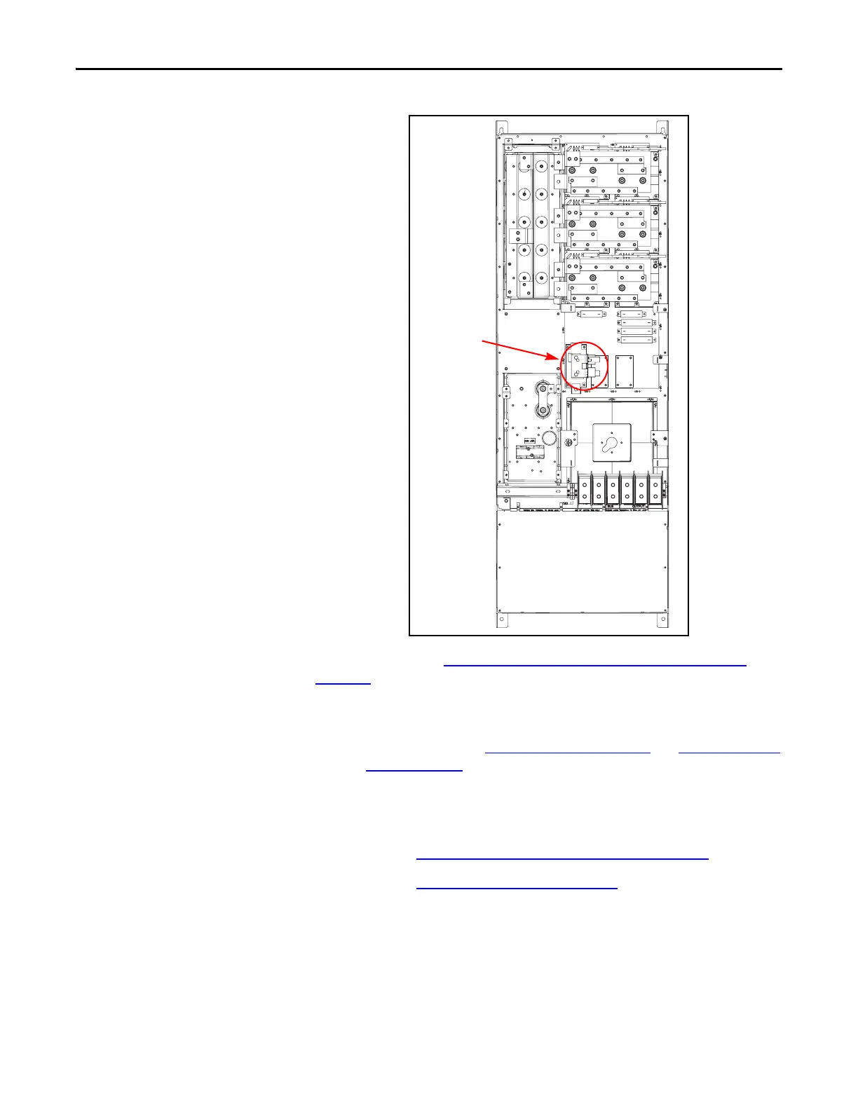
Precharge SCR Module
Snubber Board - DC Input
Only
Figure 5 - Precharge SCR Module Location (DC Input Drive Shown)
Refer to the figures in Component Diagrams and Torque Specs on page 13 and
Figure 5 -
above for these instructions.
Remove Components
1. Read and follow the Safety Precautions on page 9 and Important Initial
Steps on page 11.
2. Locate the Precharge SCR module Snubber Board to be replaced.
3. Remove the upper and lower safety shields.
4. Perform Remove Main Control Panel Assembly on page 21
.
5. Perform Remove Stacking Panel on page 22
.
6. Remove the push-on lead from the Snubber Board.
7. Unscrew and remove the Snubber Board from its bus bar. Set aside.
Precharge SCR
Module and
Snubber

 Loading...


