Rockwell Automation Publication 20B-IN017B-EN-P - September 2011 57
Component Replacement Procedures Chapter 3
Install Components
1. Replace washers on Snubber Board Bus Bar studs.
2. Replace insulation over washers.
3. Place new Snubber Board over insulation.
4. Install M6 nuts on studs with star washer side facing Snubber Board. Do
not tighten yet.
5. Center insulation around washers so it is not pinched between the Bus
Bar and any washer or nut.
6. Torque M6 nuts to 2.9 N•m (26 lb•in)
7. Replace push-on wire.
8. Reassemble remaining components in reverse order.
9. Replace all safety shields and enclosure covers before applying power to
the drive.
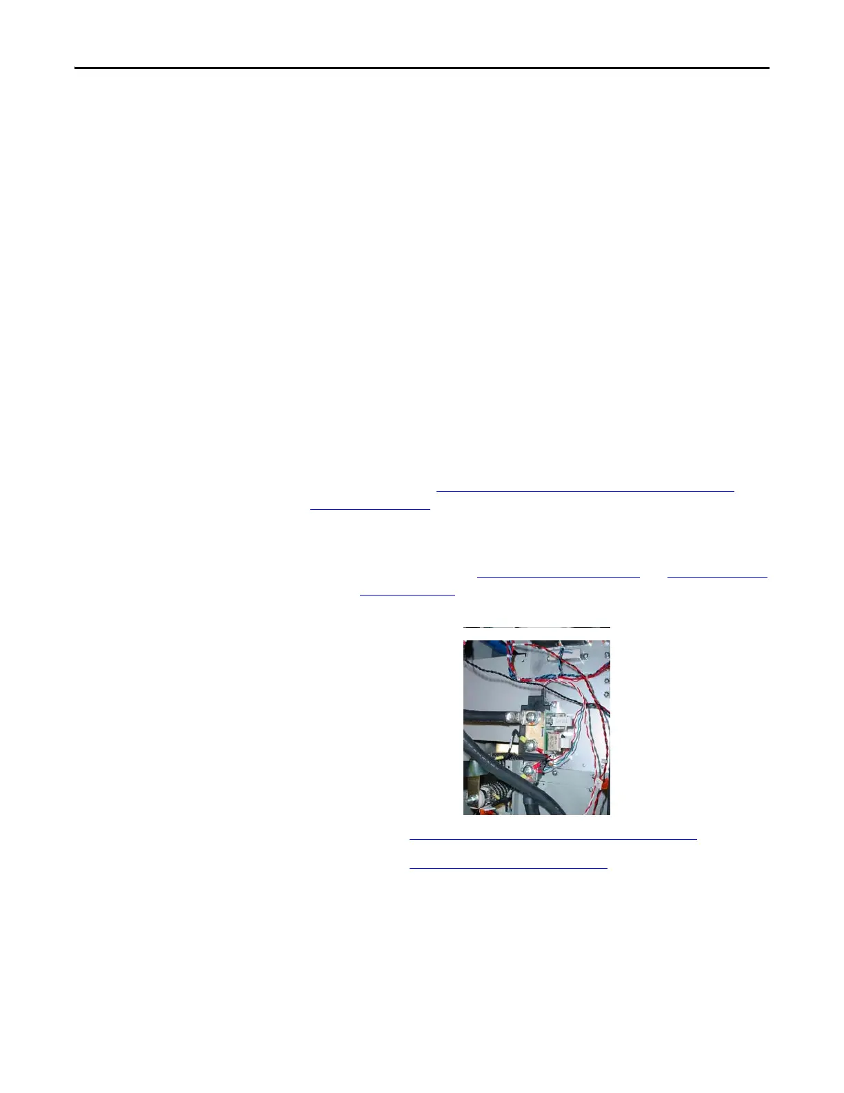
Precharge SCR Module - DC
Input Only
Refer to the figures in Component Diagrams and Torque Specs on page 13 and
Figure 5 - on page 56
for these instructions.
Remove Components
1. Read and follow the Safety Precautions on page 9 and Important Initial
Steps on page 11.
2. Locate the Precharge SCR module to be replaced.
3. Perform Remove Main Control Panel Assembly on page 21
.
4. Perform Remove Stacking Panel on page 22
.
5. Label and remove power cables (DC+ and DC–) and all connected
wires from the SCR module.
6. Remove the entire Snubber Board Bus Bar assembly, including its lead
wires, and carefully set assembly aside.
7. Remove the SCR module and discard.

 Loading...


