58 Rockwell Automation Publication 20B-IN017B-EN-P - September 2011
Chapter 3 Component Replacement Procedures
Install Components
1. Clean the surface of the Heatsink mounting surface with isopropyl
alcohol.
2. Thoroughly clean the mounting surface of the new SCR module and
apply a thin even coating of the supplied thermal grease.
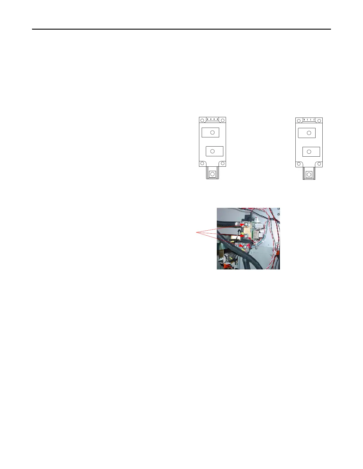
3. Install SCR module with supplied screws and torque using the sequence
and specifications shown in the diagram below.
4. Install the Snubber Board Bus Bar and assembly with its lead wires and
the DC cables (both positive) as shown below. Hold the lead wires in
place while you torque DC cable screws to 12.2 N•m (108 lb•in)
5. Reassemble remaining components in reverse order.
6. Replace all safety shields and enclosure covers before applying power to
the drive.
➊➌
➍➋
SCR Torque
First Sequence:
0.7 N-m (6.0 lb.-in.)
SCR Torque
Final Sequence:
5.6 N-m (50 lb.-in.)
➌
➍➋
➊
Torque DC cables to 12.2
N•m (108 lb•in)
Shown with Phillips
screws, but may be hex
nuts.

 Loading...


