30 Rockwell Automation Publication 20B-IN017B-EN-P - September 2011
Chapter 3 Component Replacement Procedures
Switch Mode Power Supply
Board
Refer to the figures in Component Diagrams and Torque Specs on page 13 for
these instructions.
Remove Components
1. Perform Remove Main Control Panel Assembly on page 21.
2. Disconnect all cables (J2, J4, J3, J1) from the Switch Mode Power
Supply Board.
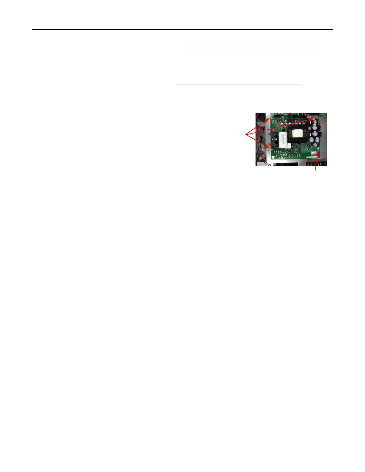
3. Remove the Switch Mode
Power Supply Board
mounting star screw
located at the lower right
corner of the board.
4. Using your fingers or
needle-nose pliers, squeeze
the wings of each of the
three spacers and separate
the Switch Mode Power Supply Board from the mounting plate.
5. Remove the Switch Mode Power Supply Board.
Install Components
1. Install the new Switch Mode Power Supply Board.
Tighten board screws to 1.7 N•m (15 lb•in)
2. Reconnect all cables.
3. Reassemble all components in the reverse order of removal.
Tighten sheet metal screws to 3.2 N•m (28 lb•in)
4. Reconnect the ribbon cable going from the Power Interface Board (J1)
to the Main Control Board (J2).
5. Replace all safety shields and enclosure covers before applying power to
the drive.
Screw
Spacers

 Loading...


