Rockwell Automation Publication 20B-IN017B-EN-P - September 2011 29
Component Replacement Procedures Chapter 3
6. If needed, use the same flathead screwdriver tip to pry the seven locking
tabs away from the T-Comm Board.
7. Remove the T-Comm Board from the Main Control Board; return or
dispose of it properly.
Install Components
1. Install the new T-Comm Board.
2. Verify the board is locked into all seven locking tabs.
3. Carefully bend the T-Comm grounding tab until it is flush with the screw
mount on the Main Control Board.
4. Reassemble all components in the reverse order of removal.
5. Reconnect all cables, safety shields and enclosure covers before applying
power to the drive.
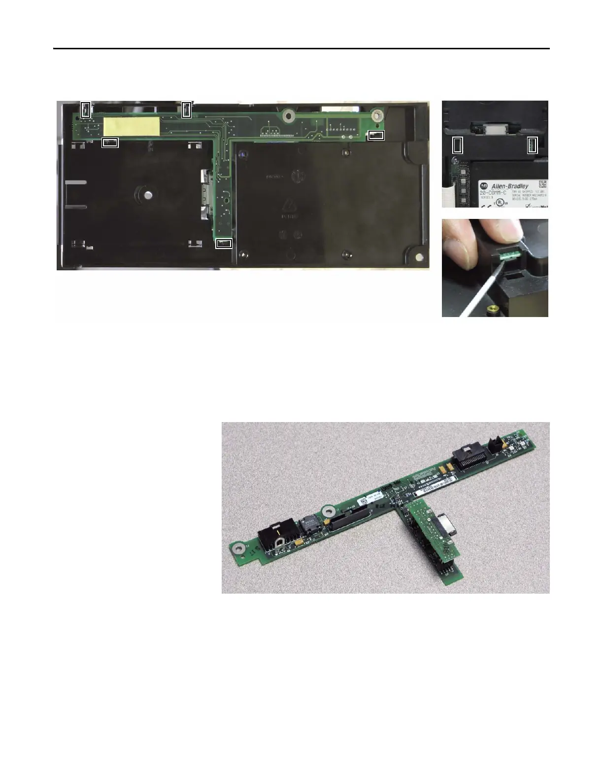
T-Comm Board Locking Tab Locations
Five locking tabs are on the back side of the Main Control Board (above); two are on the front side in the area between
the optional HIM and 20-Comm-x board slots (upper right).
NOTE: Use a flathead screwdriver tip to pry the locking tabs away from the T-Comm Board (lower right).

 Loading...


