28 Rockwell Automation Publication 20B-IN017B-EN-P - September 2011
Chapter 3 Component Replacement Procedures
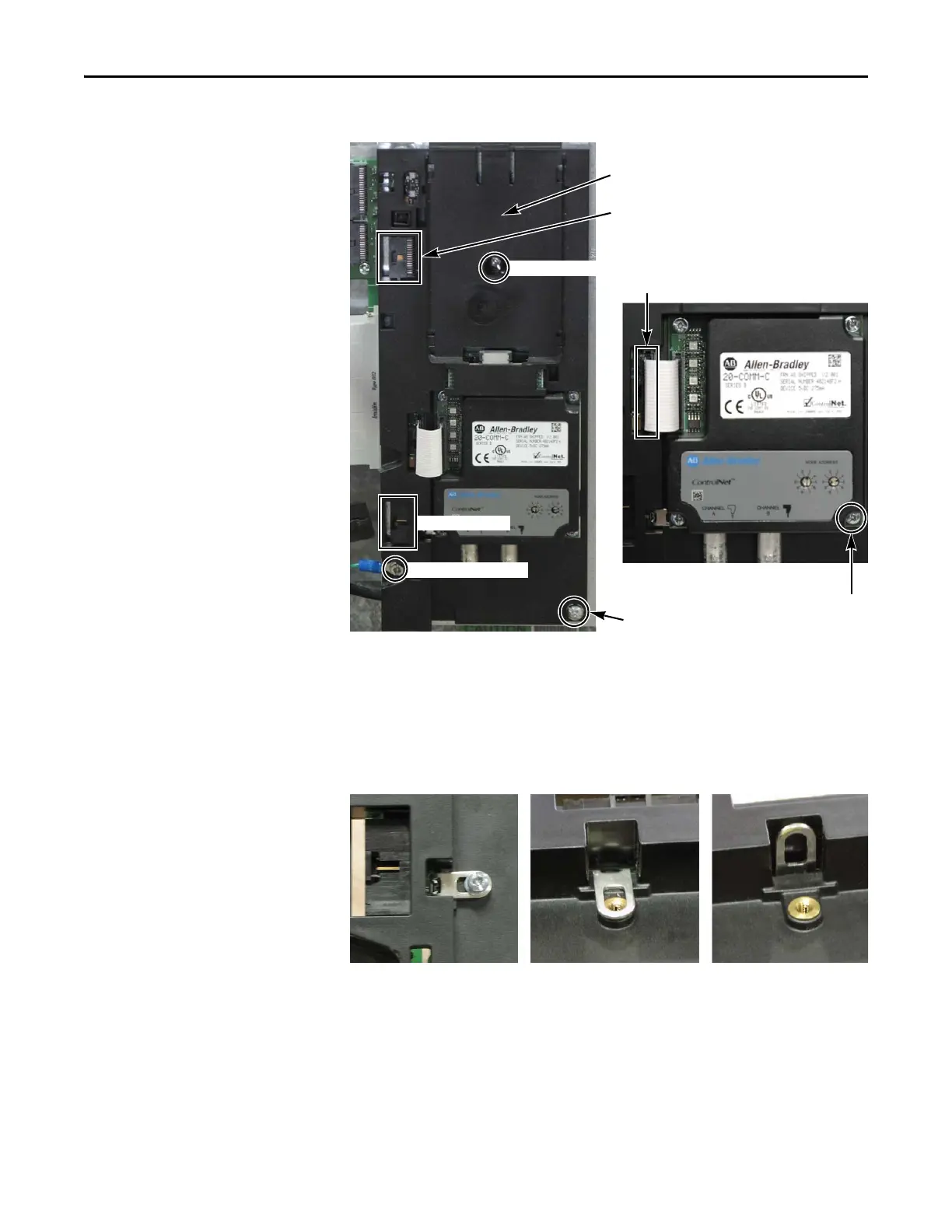
f. Remove the Main Control Board.
3. Remove the 20-Comm-x Board (if used):
a. Disconnect the ribbon cable between the 20-Comm-x Board and
T-Comm board; disconnect only from the T-Comm board.
b. Remove and save the four mounting screws.
4. If the 20-Comm-x Board is not used, remove the screw securing the
T-Comm grounding tab.
5. Place the tip of a flathead screwdriver between the T-Comm grounding
tab and screw mount.
Gently pry up until the grounding tab is in an upright position or about 90
degrees from the screw mount.
HIM Board slot
Mounting Screw
Optional 20-Comm-x Board Detail
Ribbon Cable Connector
Grounding-Wire Screw
Wiring Connector
Ribbon Cable Connection to T-Comm Board
Mounting Screws (4)
Mounting Screw
T-Comm grounding tab screw T-Comm grounding tab flat T-Comm grounding tab upright

 Loading...


