Rockwell Automation Publication 20D-PM001D-EN-P - March 2019 105
Programming and Parameters Chapter 2
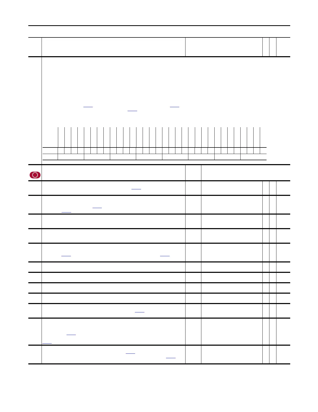
741 Position Status
Indicates status of position control algorithms.
• Bit 0 “X IGain LLim” indicates the position integrator is at the low limit.
• Bit 1 “X IGain HLim” indicates the position integrator is at the high limit.
• Bit 2 “X Spd LLim” indicates the position regulator output at the low limit.
• Bit 3 ”X Spd HLim” indicates the position regulator output is at the high limit.
• Bit 4 “PtPtRRef Act” (TBD)
• Bit 5 “XOffRRef Act” (TBD)
• Bit 7 “Regulator On” indicates position regulator is active.
• Bit 8 “Posit Watch1” indicates Position Watch 1 has detected motor position equal to its setpoint, from the proper direction.
• Bit 9 “Posit Watch2” indicates Position Watch 2 has detected motor position equal to its setpoint, from the proper direction.
• Bit 10 “In Position” indicates Par
769 [Position Error] is within the position deadband specified by Par 782 [In Posit BW].
• Bit 13 “HomeRequired” - Set when the “Find Home” bit is set in Par
740 [Position Control] and the drive is waiting on a Start command.
• Bit 14 “Homing” - Set when the drive is running the Homing Sequence.
• Bit 15 “Homed” - Set when the Homing Sequence has completed.
Note: Bits 13 - 15 were added for future use - not active for use with firmware version 3.001 and above.
742 Position Ref Sel
Enter a value to select the position mode and corresponding reference.
Note: This parameter was changed to non-linkable for firmware version 3.001.
Default:
Options:
1 =
0 =
1 =
“AuxPosit Ref ”
“Interpolate” 2 = “Pt to Pt”
“AuxPosit Ref ”
743 Aux Posit Ref
Supplies position reference to the position regulator when selected by Par 742 [Posit Ref Sel] = 1. This input is
designed to be linked to a position count accumulator such as a virtual encoder or hardware accumulator.
Default:
Min/Max:
0
-/+2147483648
Y
RW 32-bit
Integer
744 PositRef EGR Out
Accumulated output of the position reference Electronic Gear Ratio (EGR). When the position regulator is not
enabled, this parameter is initialized to Par
762 [Position Fdbk] or to the selected position reference as
determined by Par 740 [Position Control] bit 6.
Default:
Min/Max:
0
-/+2147483648
RO 32-bit
Integer
745 PositRef EGR Mul
An integer value in the numerator of the EGR function that is precision multiplied by the selected position
reference. A negative value will effect a change in polarity.
Default:
Min/Max:
1
-/+2000000
Y
RW 32-bit
Integer
746 PositRef EGR Div
An integer value in the denominator of the EGR function that divides into the product of the numerator and the
selected position reference. Remainders are accumulated and not lost.
Default:
Min/Max:
1
1/2000000
Y
RW 32-bit
Integer
747 Position Cmmd
Final accumulated command to the position regulator. When the position regulator is not enabled, this parameter
is initialized to Par 762 [Position Fdbk] or to the selected position reference as determined by Par 750 [Position
Control] bit 6. Thereafter, its value will reflect the result of reference and offset changes.
Default:
Min/Max:
0
-/+2147483648
RO 32-bit
Integer
748 CoarsePosit Trgt
Input to the interpolator. This is a coarse position target reference.
Default:
Min/Max:
0
-/+2147483648
Y
RW 32-bit
Integer
749 Interp Position
Input to the interpolator. This is a fine position target reference.
Default:
Min/Max:
0
-/+2147483648
RO 32-bit
Integer
750 Coarse Spd Trgt
Input to the interpolator. This is a coarse speed target reference.
Default:
Min/Max:
0
-/+2200000000.0000
Y
RW Real
751 Interp Speed
Output from the interpolator. This is a fine speed target reference.
Default:
Min/Max:
0
-/+8.0000 P.U.
RO Real
752 Interp AccelRate
Output from interpolator. This is a fine acceleration rate. First derivative of Par 750 [Course Spd Trgt] if available, or
zero (0) if not available.
Default:
Min/Max:
0
-/+8.0000 P.U.
RO Real
753 Posit Offset 1
Supplies a position reference offset, which is summed after the EGR and used to phase trim position reference. A
step in the offset position will be internally rate limited and added to the selected reference position. The rate of
correction is set by Par
755 [Posit Offset Spd]. The initial value of this parameter is latched upon position enable
without causing a change in reference. Subsequent changes to this value will be relative to the latched value. See
Par
740 [Position Control], bit 5 for re-referencing the offsets.
Default:
Min/Max:
0
-/+2147483648
Y
RW 32-bit
Integer
754 Posit Offset 2
Supplies another position reference offset, which is summed with Par 753 [Posit Offset 1]. Used to trim the phase
of the selected position reference. Position offset will be internally rate limited to a velocity set by Par
755 [Posit
Offset Spd].
Default:
Min/Max:
0
-/+2147483648
Y
RW 32-bit
Integer
No. Name
Description
Values
Linkable
Read-Write
Data Type
Options
Reserved
Reserved
Reserved
Reserved
Reserved
Reserved
Reserved
Reserved
Reserved
Reserved
Reserved
Reserved
Reserved
Reserved
Reserved
Reserved
Homed
Homing
HomeRequired
Reserved
Posit Out En
In Position
Posit Watch2
Posit Watch1
Regulator On
Reserved
XOffRRef Act
PtPtRRef Act
X Spd HLim
X Spd LLim
X IGain HLim
X IGain LLim
Default xxxxxxxxxxxxxxxx000x00010x000010
Bit 313029282726252423222120191817161514131211109876543210
0 = False
1 = True
 Loading...


