198 Rockwell Automation Publication 20D-PM001D-EN-P - March 2019
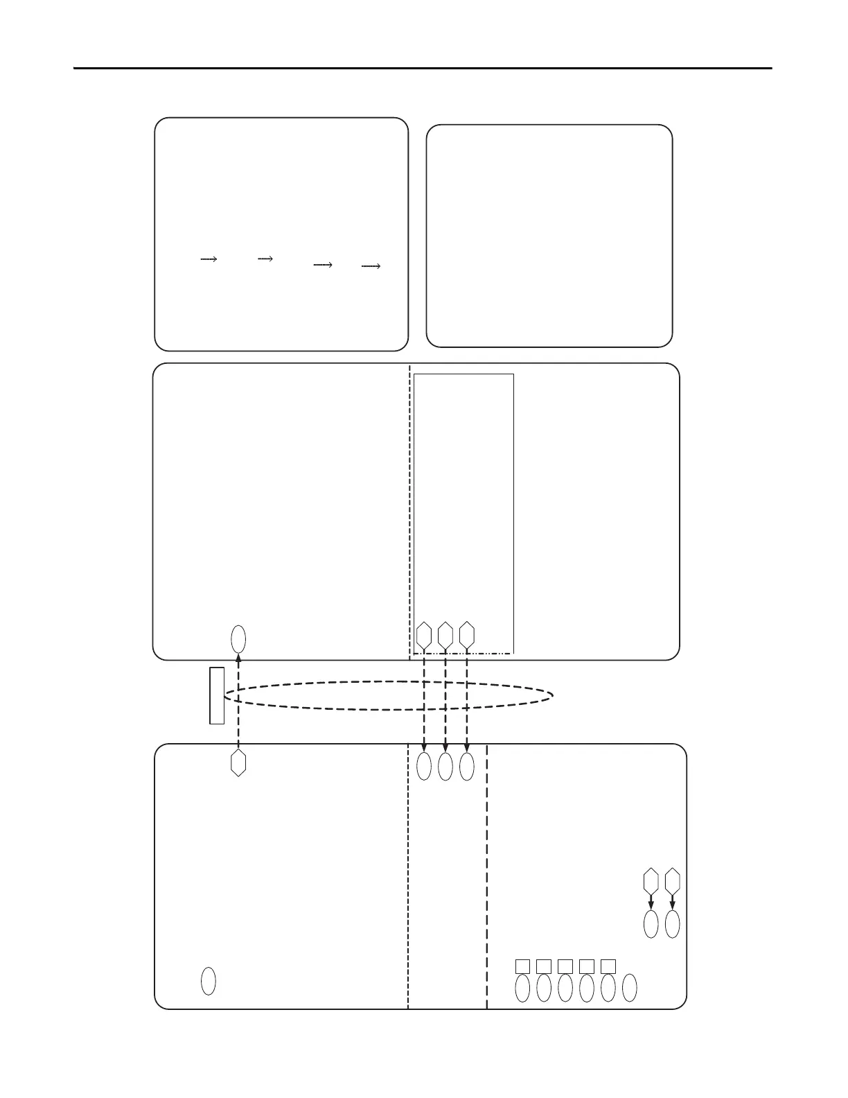
Appendix C Control Block Diagrams
PowerFlex 700S Phase 2
DriveLogix-Motion Control
DriveLogixDrive Control
698
699
700
FromDriveLogix00 –Motion Planner Coarse Positon
FromDriveLogix01 – Motion Planner Coarse Speed
FromDriveLogix02 – Motion Planner Synch
748
750
693
CoarsePosit Trgt
Coarse Spd Trgt
Intrp SyncInput
155 626
To DriveLogix00 – Logix Tag “LogicStatus”Logic Status
600
Lgx Comm Format = 19 “Motion Ctrl”
Links
Undefined Available Connections
From DriveLogix UserDefinedRealData[0]
From DriveLogix UserDefinedRealData[11]
From DriveLogix UserDefinedIntegerData[0]
From DriveLogix UserDefinedIntegerData[8]
To DriveLogix UserDefinedRealData[0]
To DriveLogix UserDefinedRealData[2]
To DriveLogix UserDefinedIntegerData[0]
To DriveLogix UserDefinedIntegerData[2]
To DriveLogix
From DriveLogix
147
151
740
740
740
742
22
12
=1 Positon Control Firmware Enable
16
13
1
6
8
=1 Position Loop Enable
= 1 Interpolator Enable
= 0 AbsPositCtrl must be off for Motion Control
= 0 Xzero Preset must be off for Motion Control
= 0 Position Ref Sel
318
751
Speed Trim 2 Posit Spd Output
Interp SpeedSpeed Ref 2
**
**
These Parameters must be set or the
DriveLogix will show a “Module not Configured”
Error for the drive I/O connection.
***
P904 bit 0 = 1 must be set to “Time Keeper” or
receive it from another SynchLink device for the
Motion Connection. If it is not set or received the
software reports a CST erro.
P146 = 0 Position Loop must run in the 2 ms task in
order to match the only configuration in Version 13
of RSLogix5000.
These do not show up in the Controller or Program Tags
 Loading...


