Rockwell Automation Publication 20D-PM001D-EN-P - March 2019 51
Programming and Parameters Chapter 2
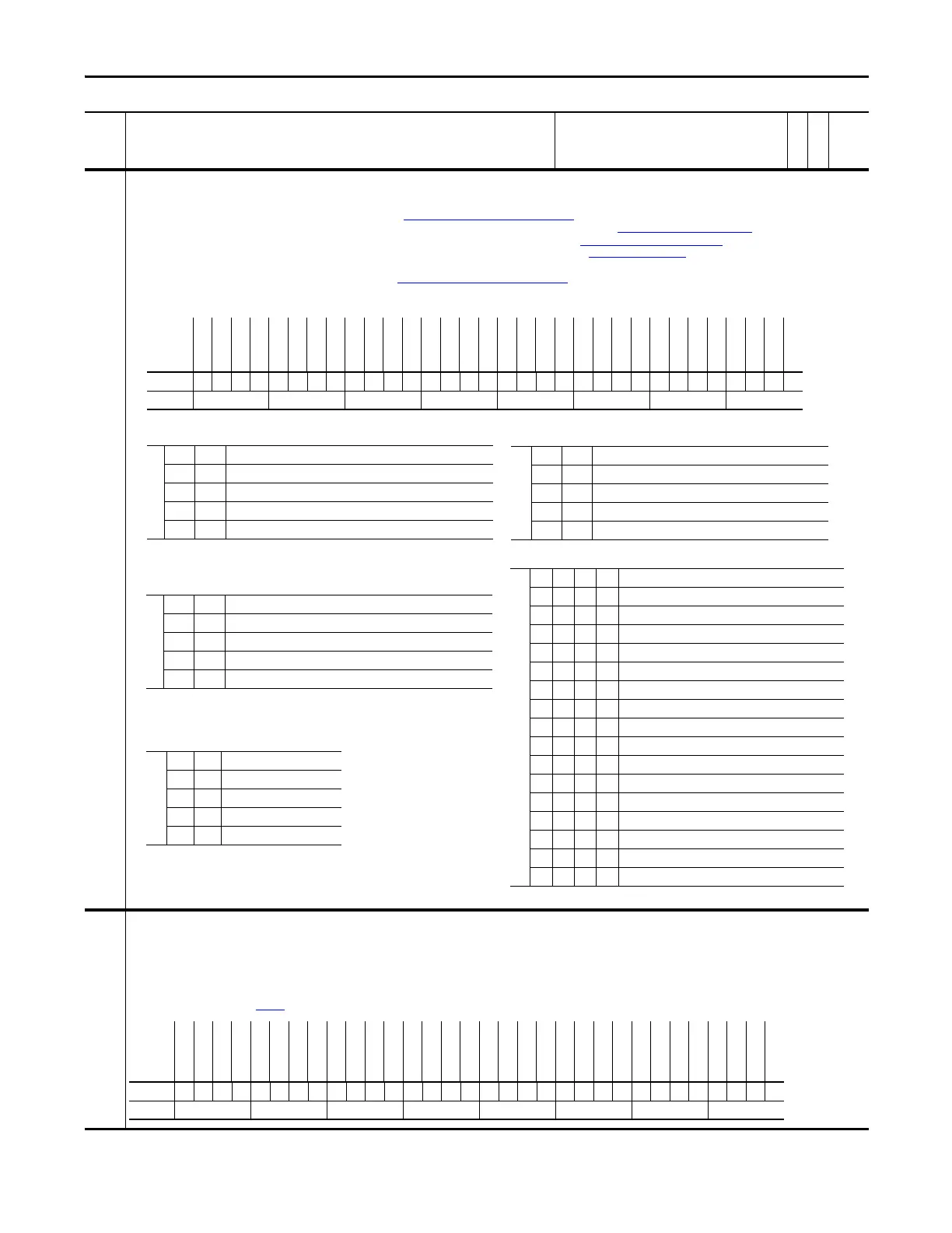
236 RegisLtch 0/1Cnfg
Configures the registration latch at port 0 or port 1 to be used with Encoder 0 or Encoder 1, respectively.
• Bit 0 “RL0 Encoder 1” selects the encoder for the input source of latched data. Setting bit 0 selects encoder 1, resetting the bit to zero selects encoder 0.
• Bits 1 “RL0 TrgSrc0” and 2 “RL0 TrgSrc1” select the trigger source (see Table 236A: Encoder0 Trigger Source Settings
).
• Bits 3 “RL0 TrgEdge0”, 4 “RL0 TrgEdge1”, 19 “RL1 TrgEdge0” and 20 “RL1 TrgEdge1” select which edges signal the position (see Table 236C: Edge Selection Settings).
• Bits 5 “RL0 Dir Rev”, 6 “RL0 Dir Fwd”, 21 “RL1 Dir Rev” and 22 “RL1 Dir Fwd” set the direction of position capture (see Table 236D: Trigger Direction Settings
).
• Bits 8 “SL DI Filt 0”, 9 “SL DI Filt 1”, 10 “SL DI Filt 2”, and 11 “SL DI Filt 3” configure a filter for the digital input 1 and 2 (see Table 236E: Filter Settings
). The filter requires the input signal to be stable
for the specified time period. Input transitions within the filter time setting will be ignored. Bits 8-11 add 100ns filter per stage to external trigger.
• 17 “RL1 TrgSrc0” and 18 “RL1 TrgSrc1” select the trigger source (see Table 236B: Encoder1 Trigger Source Settings
).
• Bit 0 &16 - off = Enc0 input to latch, on = Enc1 input to latch.
237 RegisLtch0/1 Ctrl
Configures the control for registration latch 0 and 1.
• Set bit 0 “RL0 Arm Req” and bit 16 “RL1 Arm Req” to arm the registration logic for the next trigger event. The particular latch will be armed and ready to be strobed on the next occurrence of the
trigger input.
• Set bit 1 “RL0 DisarmReq” and bit 17 “RL1 DisarmReq” to disarm the registration logic for next trigger event.
After the registration is captured, bit 0 “RL0 Arm Req” and bit 16 “RL1 Arm Req” automatically resets back to 0 after found. Bit 1 “RL0 DisarmReq” and bit 17 “RL1 DisarmReq” are only needed to
disarm a registration latch that has not been found yet. Setting bits 1 and 17 will clear the bits 0 and 6. Setting bits 0 and 6 sets bits 0 “RL0 Armed” and bit 16 “RL1 Armed” and clears bits 1 “RL0
Found” and bit 17 “RL1 Found” of Par
238 [RegisLtch0/1Stat].
No. Name
Description
Values
Linkable
Read-Write
Data Type
Table 236A: Encoder0 Trigger Source Settings
Note: When the Z-pulse is selected as a trigger source, registration latch port 0 is used for
Encoder0 regardless of the setting of bit 0 “RL0 Encoder1”.
Bit 2 1
0 0 Encoder 0 Z-pulse AND Ext Trig A
0 1 Ext Trig B (Digital Input 2)
1 0 Ext Trig A (Digital Input 1)
1 1 Encoder 0 (Primary Encoder) Z-pulse
Table 236D: Trigger Direction Settings
Bit 6/22 5/21
00Not Configured
01Reverse
10Forward
11Both Directions
Table 236E: Filter Settings
Bit 11 10 9 8 Input Filter Setting
0000Filter disabled
0001100 ns filter
0010200 ns filter
0011300 ns filter
0100400 ns filter
0101500 ns filter
0110600 ns filter
0111700 ns filter
1000800 ns filter (default setting)
1001900 ns filter
10101000 ns filter
10111100 ns filter
11001200 ns filter
11011300 ns filter
11101400 ns filter
11111500 ns filter
Options
Reserved
Reserved
Reserved
Reserved
Reserved
Reserved
Reserved
Reserved
Reserved
RL1 Dir Fwd
RL1 Dir Rev
RL1 TrgEdge1
RL1 TrgEdge0
RL1 TrgSrc1
RL1 TrgSrc0
RL1 Encoder1
Reserved
Reserved
Reserved
Reserved
SL DI Filt 3
SL DI Filt 2
SL DI Filt 1
SL DI Filt 0
Reserved
RL0 Dir Fwd
RL0 Dir Rev
RL0 TrgEdge1
RL0 TrgEdge0
RL0 TrgSrc1
RL0 TrgSrc0
RL0 Encoder1
Default xxxxxxxxx0000000xxxx0000x1100011
Bit 313029282726252423222120191817161514131211109876543210
Table 236C: Edge Selection Settings
Bit 4/20 3/19
0 0 Capture on rising edge
0 1 Capture on falling edge
1 0 Capture on both edges
1 1 Disable capture
0 = False
1 = True
Table 236B: Encoder1 Trigger Source Settings
Note: When the Z-pulse is selected as a trigger source, registration latch port 1 is used for
Encoder1 regardless of the setting of bit 16 “RL1 Encoder1”.
Bit 18 17
0 0 Encoder 1 Z-pulse AND Ext Trig A
0 1 Ext Trig B (Digital Input 2)
1 0 Ext Trig A (Digital Input 1)
1 1 Encoder 1 (Secondary Encoder) Z-pulse
Options
Reserved
Reserved
Reserved
Reserved
Reserved
Reserved
Reserved
Reserved
Reserved
Reserved
Reserved
Reserved
Reserved
Reserved
RL1 DisarmReq
RL1 Arm Req
Reserved
Reserved
Reserved
Reserved
Reserved
Reserved
Reserved
Reserved
Reserved
Reserved
Reserved
Reserved
Reserved
Reserved
RL0 DisarmReq
RL0 Arm Req
Default xxxxxxxxxxxxxx00xxxxxxxxxxxxxx00
Bit 313029282726252423222120191817161514131211109876543210
0 = False
1 = True
 Loading...


