EasyManuals Logo

Rockwell Automation Allen-Bradley PowerFlex 755T Installation Instructions

Rockwell Automation Allen-Bradley PowerFlex 755T
130 pages
To Next Page IconTo Next Page
To Previous Page IconTo Previous Page
Page #56 background imageLoading...
Page #56 background image
56 Rockwell Automation Publication 750-IN118A-EN-P - May 2021
Chapter 3 Mechanical and Electrical Installation
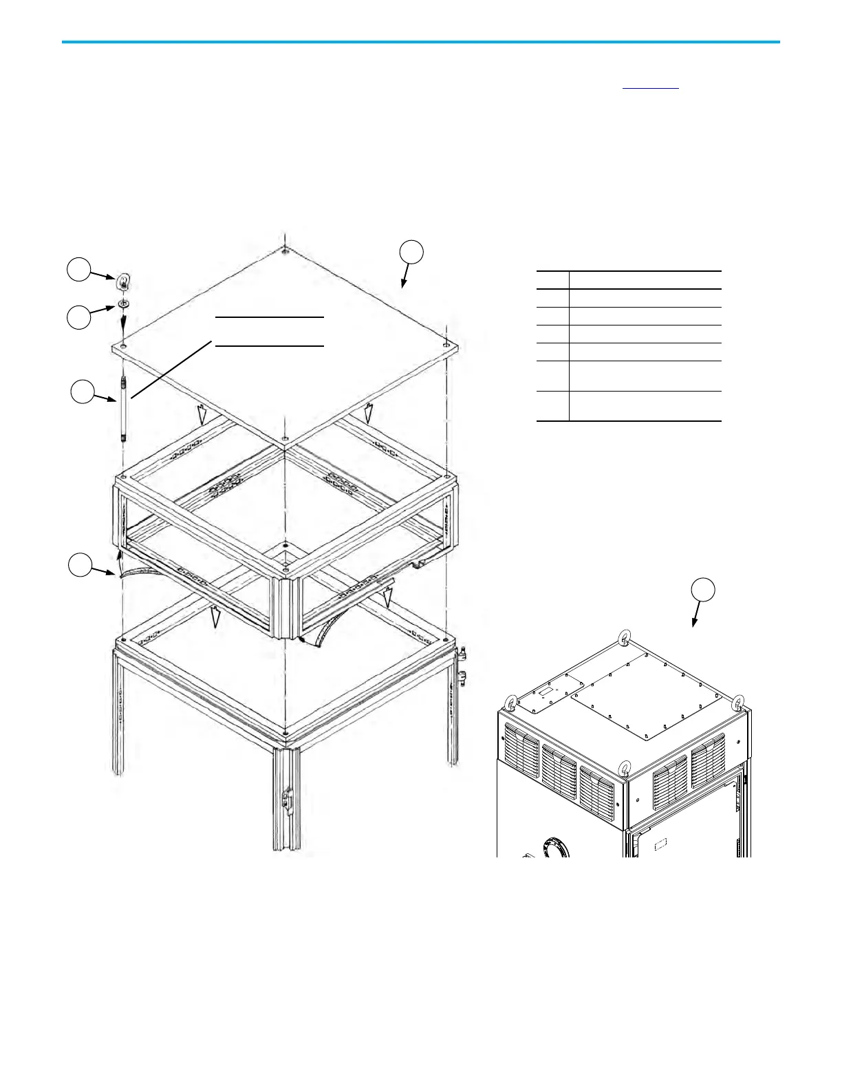
2. Apply the gaskets that came with the exhaust hood onto the mating
surface between the exhaust hood and the bay (Figure 53, item 4).
3. Lower the exhaust hood onto the bay.
4. Connect the rings of the two-part eye bolts to the rods of the two-part eye
bolts.
5. Use the two-part eye bolts and washers to attach the exhaust hood to the
bay.
Figure 53 - Installing the Three-front-vent Exhaust Hood
1
2
3
4
6
5
Item Description
1 Ring of a two-part eye bolt
2Washer
3 Rod of a two-part eye bolt
4Gasket
5
Base structure view (side walls,
panels, and bay doors not shown)
6
Final assembled three-front-vent
exhaust hood
M12
20.0 N•m (177 lb•in)

Table of Contents

Other manuals for Rockwell Automation Allen-Bradley PowerFlex 755T

Questions and Answers:

Question and Answer IconNeed help?

Do you have a question about the Rockwell Automation Allen-Bradley PowerFlex 755T and is the answer not in the manual?

Rockwell Automation Allen-Bradley PowerFlex 755T Specifications

General IconGeneral
BrandRockwell Automation
ModelAllen-Bradley PowerFlex 755T
CategoryDC Drives
LanguageEnglish

Related product manuals