Rockwell Automation Publication 750-IN118A-EN-P - May 2021 63
Chapter 3 Mechanical and Electrical Installation
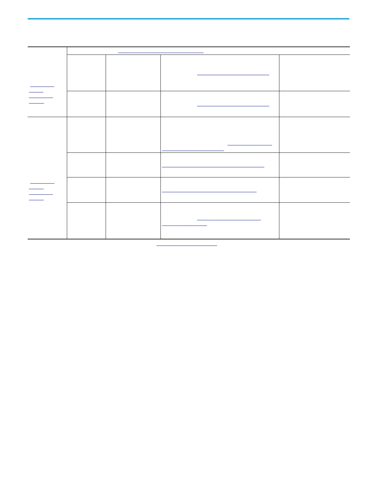
Configured input
bay with circuit
breaker, top or
bottom entry
(Figure 73 on
page 79 and
Figure 74 on
page 80)
All connections in frame 9 Configured input bay, control-only on page 62
AC power input
terminals on
circuit breaker
Customer AC power source Power cables with Terminal Lug Connections on page 100
• The terminal lugs are connected
to the circuit breaker.
• The cables are provided by the
customer, and must be
connected to the terminal lugs
during installation.
AC power output
terminals on
circuit breaker
Drive AC power input
busbar
Power cables with Terminal Lug Connections on page 100
• Inside the configured input bay
• Connected to the circuit breaker
• Must be connected to the drive
input bay during installation
Configured output
bays with sine-
wave filters
(2)
, top
or bottom exit
(Figure 78 on
page 82 and
Figure 79 on
page 83)
Configured bay
control connectors
in configured
output bay
Configured bay control
connectors in configured
input bay
Each configured bay control connector in the configured
input bay connects to a configured bay control connector in
the configured output bay. The connection hardware for each
of these connections is a bundle of 16 AWG control cables,
with connectors on both ends. See Configured Bay Control
Connection Hardware on page 88.
• Inside the drive bays
• Must be connected to the
configured input bay and
configured output bay during
installation
PE ground bar Drive PE ground bar PE Ground Bar Splice Connection Hardware on page 84
• Connected to configured output
bay PE ground bar, must be
connected to drive power bay PE
ground bar during installation
AC power input
busbar
Drive AC power output
busbar
AC Busbar Splice Connection Hardware on page 84
• Connected to configured output
bay AC power input busbar
• Must be connected to drive power
bay during installation
AC power output
busbar
Customer motor
Power cables with Barrel Lug to L-Bracket to Busbar
Connections on page 98
• The L-brackets are connected to
the busbar.
• The cables are provided by
customer, and must be
connected to the L-brackets
during installation.
(1) Not all grounding connections included. For grounding connections, see Grounding Requirements on page 94.
(2) With a sine-wave filter, do not use a pulse width modulation (PWM) frequency less than 2 kHz.
Table 9 - Frame 9 Configured Bays - Bay to Bay, Bay to Customer Power Source, and Bay to Customer Motor Electrical Connections Made
During Installation
(1)

 Loading...


