82 Rockwell Automation Publication 750-IN118A-EN-P - May 2021
Chapter 3 Mechanical and Electrical Installation
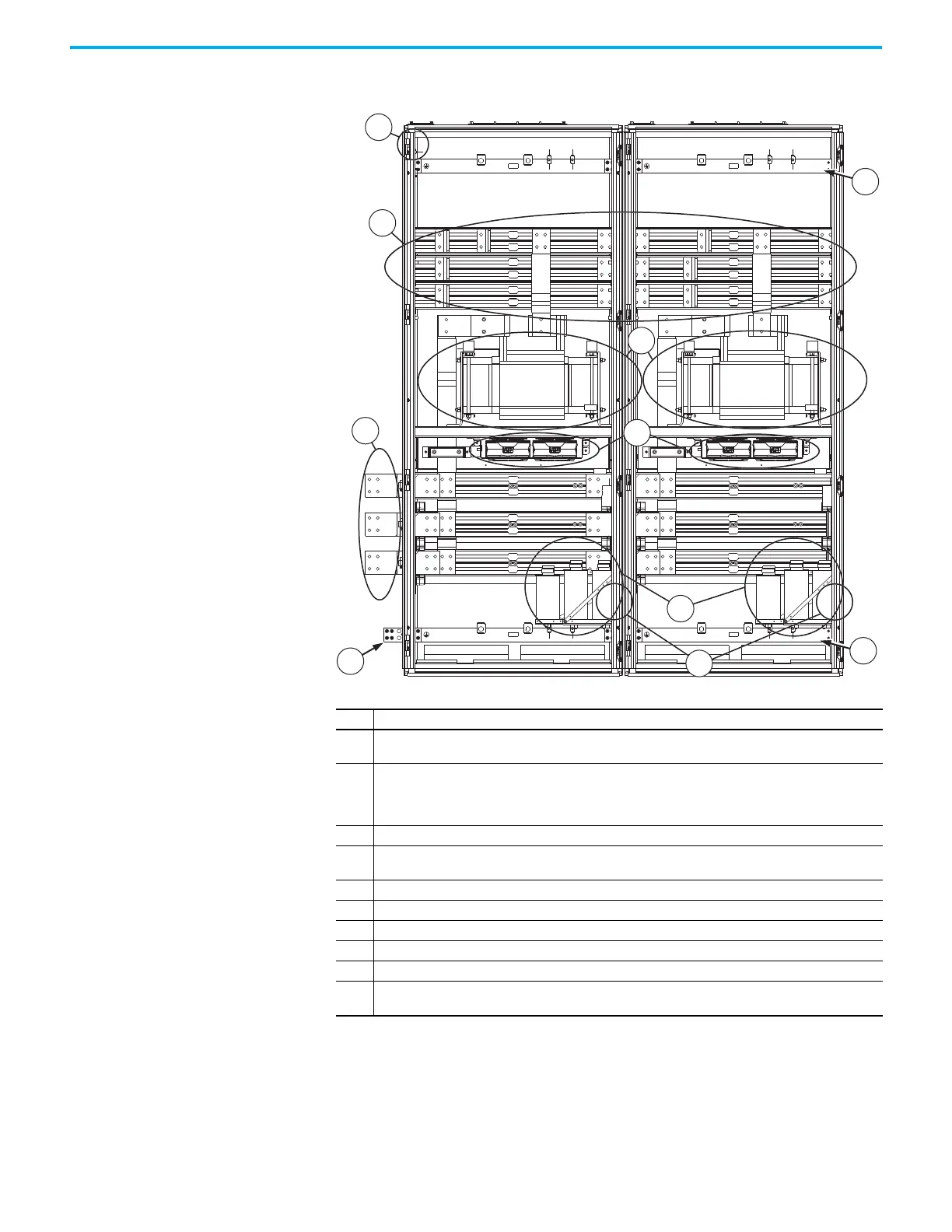
Figure 78 - Frame 9 Configured Output Bay, Top Exit: Internal Components and Installation Connection
Locations
Item Description
1
Configured bay control connectors for control connections to configured input bay (not visible in this view,
located behind bay frame). Connections must be made during installation.
2
Connections for power output to customer motor. Connected via lug to L-bracket to extruded busbar
connection. In each bay, the bottom two extruded busbars each have one 4-hole L-bracket. In the left bay,
the top extruded busbar has two 2-hole L-brackets. In the right side bay, the top extruded busbar has one
2-hole L-bracket. Connections must be made during installation.
3 AC busbar splice connection hardware for power from the drive
4
PE ground bar splice connection hardware. Ground splice connection to drive PE ground bar must be made
during installation.
5 Thermostat (not visible in this view, located behind sine-wave filter capacitor bank)
6 Sine-wave filter capacitor bank
7PE ground bar
8 Sine-wave filter reactor fan tray with four fans
9 Sine-wave filter reactor
10
PE ground bar with ground clamps included. Terminating point to chassis ground for motor and motor
cable shield. Ground connections must be made during installation.
 Loading...


