EasyManuals Logo

Rockwell Automation Allen-Bradley PowerFlex 755T Installation Instructions

Rockwell Automation Allen-Bradley PowerFlex 755T
130 pages
To Next Page IconTo Next Page
To Previous Page IconTo Previous Page
Page #81 background imageLoading...
Page #81 background image
Rockwell Automation Publication 750-IN118A-EN-P - May 2021 81
Chapter 3 Mechanical and Electrical Installation
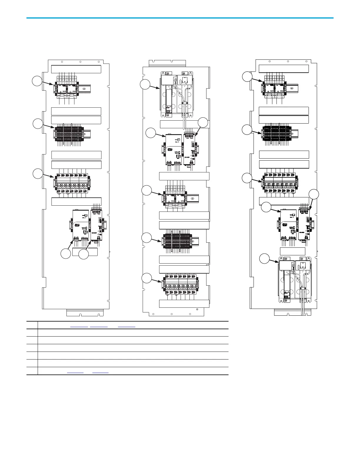
Figure 75 - Control Panel for Frame 9
Configured Input Bay Control-only or Fuses, Top
Entry
Figure 76 - Control Panel for Frame 9
Configured Input Bay with Fuses, Bottom
Entry
Figure 77 - Control Panel for Frame 9
Configured Input Bay with Circuit Breaker, Top
or Bottom Entry
Item Description (for Figure 75, Figure 76, and Figure 77)
1 Control relays
2Terminal blocks
3Fuse blocks
4 Control power supply (24V DC)
5 Uninterruptible power supply
6 Battery (only in Figure 76
and Figure 77)
1
2
3
4
5
1
2
3
5
6
4
1
2
3
4
6
5

Table of Contents

Other manuals for Rockwell Automation Allen-Bradley PowerFlex 755T

Questions and Answers:

Question and Answer IconNeed help?

Do you have a question about the Rockwell Automation Allen-Bradley PowerFlex 755T and is the answer not in the manual?

Rockwell Automation Allen-Bradley PowerFlex 755T Specifications

General IconGeneral
BrandRockwell Automation
ModelAllen-Bradley PowerFlex 755T
CategoryDC Drives
LanguageEnglish

Related product manuals