Rockwell Automation Publication 750-IN118A-EN-P - May 2021 69
Chapter 3 Mechanical and Electrical Installation
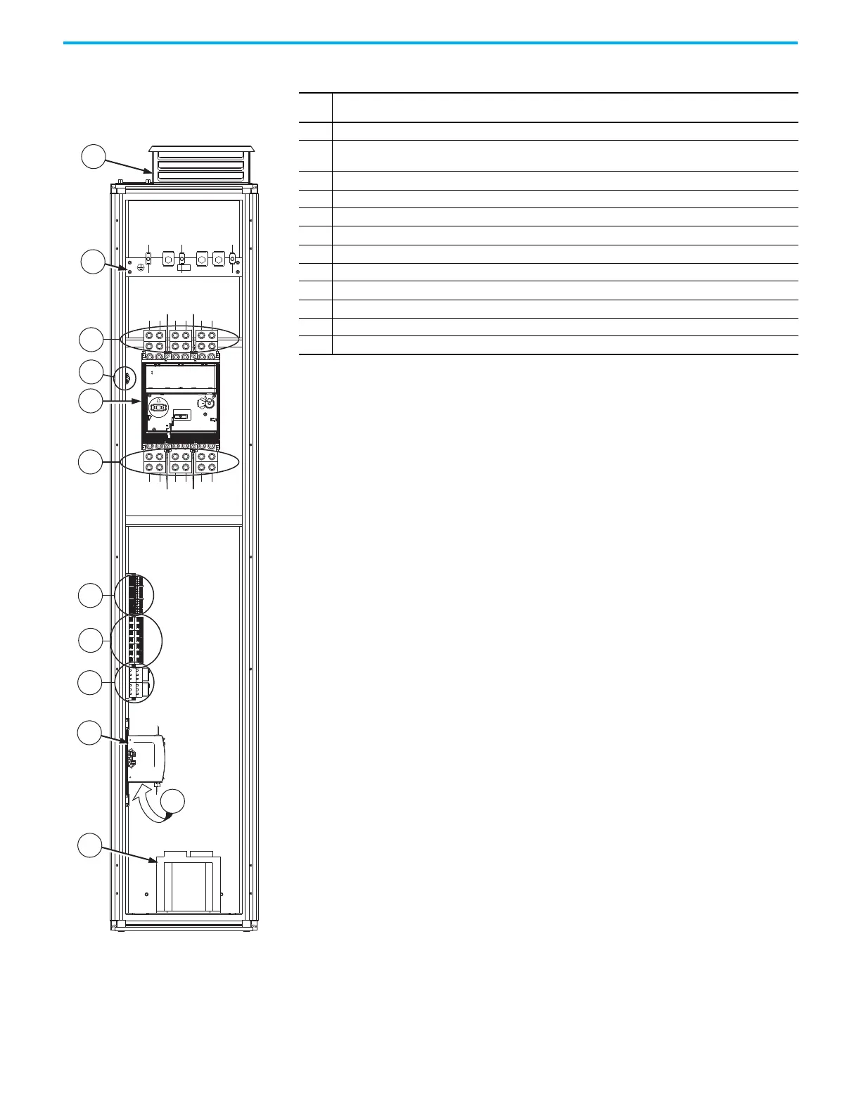
Figure 61 - Frame 8 Configured Input Bay with
Circuit Breaker, Top Entry: Internal Components
and Installation Connection Locations
Item Description
1 Roof exhaust vent with internal air filter
2
PE ground bar with ground clamps included. Terminating point to chassis ground for incoming AC line and
shield. Ground connections must be made during installation.
3 Terminal lugs for customer AC line input power. Connections must be made during installation.
4Thermostat
5 AC line input protection circuit breaker
6 Terminal lugs to supply power to the drive input bay
7 Terminal blocks
8Fuse blocks
9 Control relays
10 Control power supply (24V DC)
11 Uninterruptible power supply and battery (behind control power supply)
12 Control transformer

 Loading...


