70 Rockwell Automation Publication 750-IN118A-EN-P - May 2021
Chapter 3 Mechanical and Electrical Installation
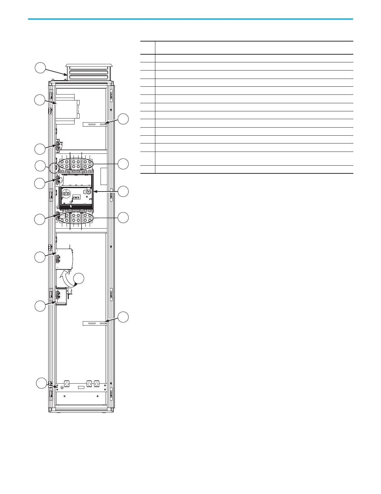
Figure 62 - Frame 8 Configured Input Bay with
Circuit Breaker, Bottom Entry: Internal Components
and Installation Connection Locations
Item Description
1 Roof exhaust vent with internal air filter
2 Control transformer
3Fuse block
4Thermostat
5 Terminal block
6 Control relay
7 Terminal lugs to supply power to the drive input bay
8 AC line input protection circuit breaker
9 Terminal lugs for customer AC line input power. Connections must be made during installation.
10 Control power supply (24V DC)
11 Uninterruptible power supply (behind control power supply)
12 Battery
13
PE ground bar with ground clamps included. Terminating point to chassis ground for incoming AC line
and shield. Ground connections must be made during installation.
14 Cable support brackets - support and guide power cables that connect to the drive input bay

 Loading...


