76 Rockwell Automation Publication 750-IN118A-EN-P - May 2021
Chapter 3 Mechanical and Electrical Installation
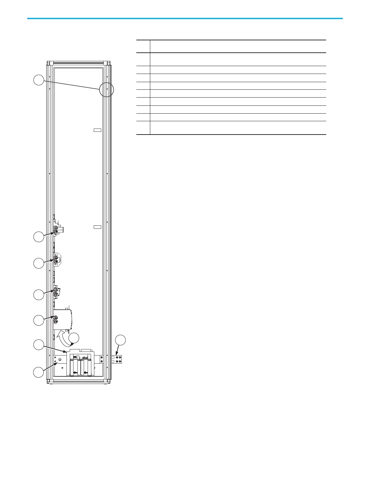
Figure 70 - Frame 9 Configured Input Bay Control-
only: Internal Components and Installation
Connection Locations
Item Description
1
Configured bay control connectors for control connections to configured output bay (not
visible in this view, located behind bay frame). Connections must be made during installation.
2 Control relays
3 Control terminal blocks
4Fuse blocks
5 Control power supply (24V DC)
6 Uninterruptible power supply, and battery (behind control power supply)
7 Control transformer
8 PE ground bar with ground clamps included
9
PE ground bar splice connection hardware. Ground splice connection to drive PE ground bar
must be made during installation.

 Loading...


