Rockwell Automation Publication 750-IN118A-EN-P - May 2021 75
Chapter 3 Mechanical and Electrical Installation
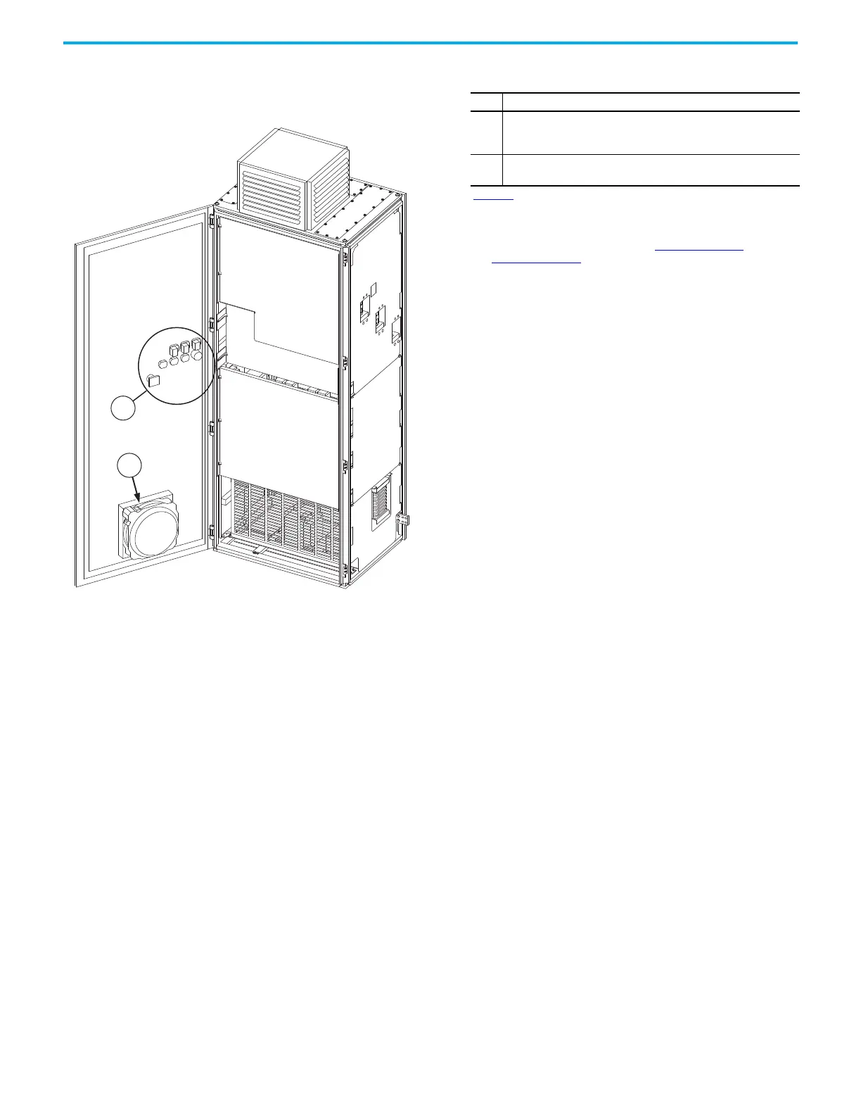
Figure 69 - Frame 8 and 9 Configured Input Bay with Input Protection Basic Door
Internal Components
Item Description
1
Wire terminals for pilot lights and controls. These terminals are
present only on configured input bays. All connections to these
terminals are made at the factory.
2
Fan with internal air filter. This fan is present on the interior of the
door for every configured input bay with input protection.
Figure 69
shows a frame 9 configured input bay with fuses, top entry. The
labeled door components are the basic door internal components common
to all frame 8 and frame 9 configured input bays with input protection. To
identify additional internal door components, see the configured input bay
upper door external component drawings, Figure 57 on page 65 for frame 8
and Figure 68 on page 74 for frame 9.

 Loading...


