Rockwell Automation Publication 750-IN118A-EN-P - May 2021 89
Chapter 3 Mechanical and Electrical Installation
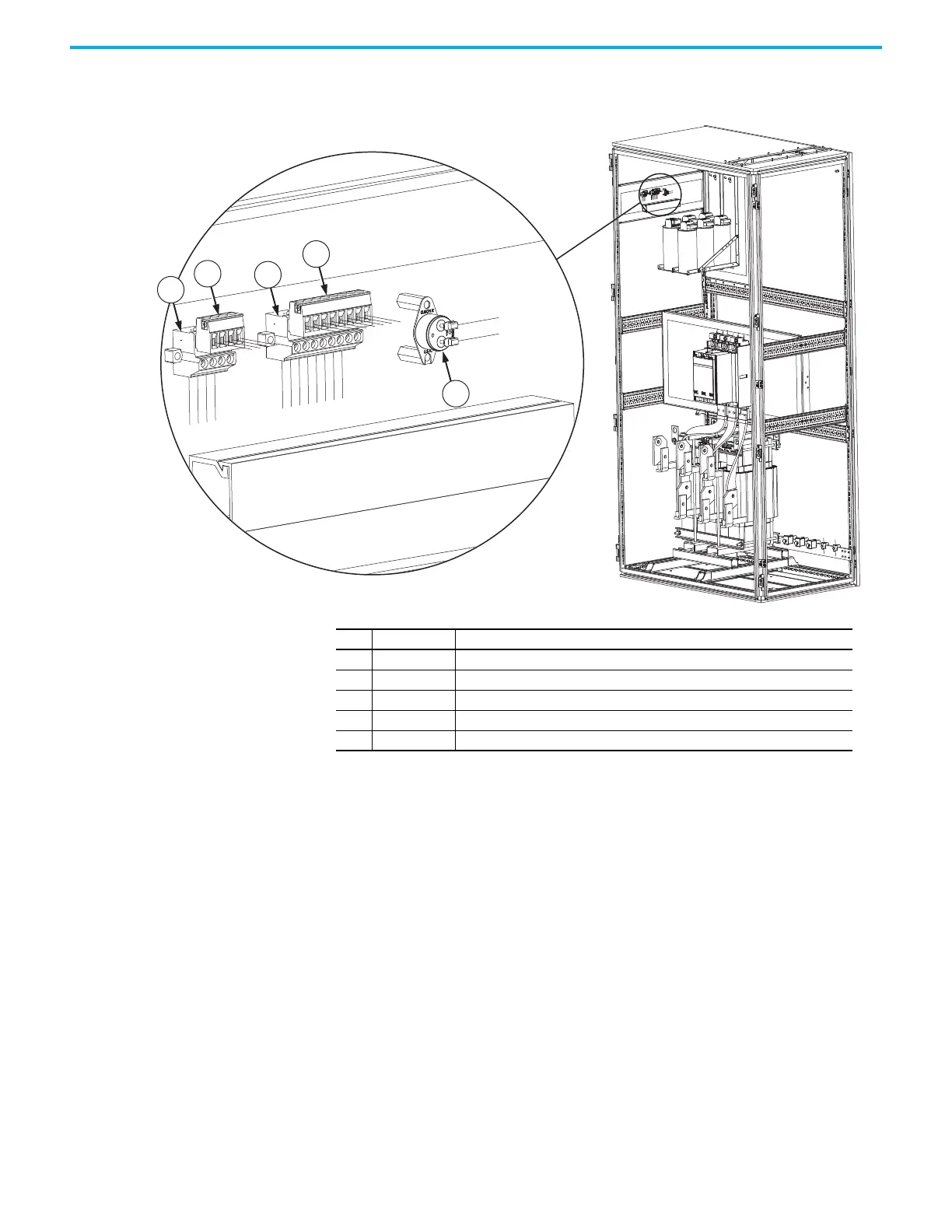
Figure 88 - Configured Bay Control Connections and Thermostat on the Frame 8 Configured Output Bay
Control Panel
Item Identification Description
1 PLUG1 Four-pole socket connector 24V DC
2 PLUG1 Four-pole plug connector 24V DC. Must connect to item 1 during installation.
3 PLUG2 Eight-pole socket connector 120V AC.
4 PLUG2 Eight-pole plug connector 120V AC. Must connect to item 3 during installation.
5TAS2 Thermostat

 Loading...


