Rolls- Royce Silver Shadow
6
Bentley
T
Series
Workshop
hnua/
C
chapter
J
washer which must
be
fitted between the belleville
washers and the bearing, to give the
correct pre-load.
Adjusting washers are available in a range from
0.200 in. to 0.260 in. (5,08
mm
to
6.60
mm.)
in
increments of
0.010 in.
(0,254
mm.).
Washers my
be
lightly ground to obtain the correct dimension but
if this is done, equal amounts must
be
removed from
each side and the washer must
be
kept bt and
parallel.
28.
Fit the right-hand side housing to the half-shaft.
29.
Fit the correct washer
with
the chamfered side
outward. Fit the three belleville washers, convex
side outward, fit the distance piece, housing and half-
shaft assembly after applying a light coating of
SQ
32M jointing compound to the flange faces.
30.
Tighten the housing securing nuts progressively
and evenly and
hally torque tighten them
in
accord-
ance with the standard figures, relative to size, given
in
Chapter
P.
31.
Torque tighten the nuts securing the two large
bearing caps
in
accordance with the standard figures
given in Chapter
P.
32.
Remove the stiffening bar
(RH
8032), fit the
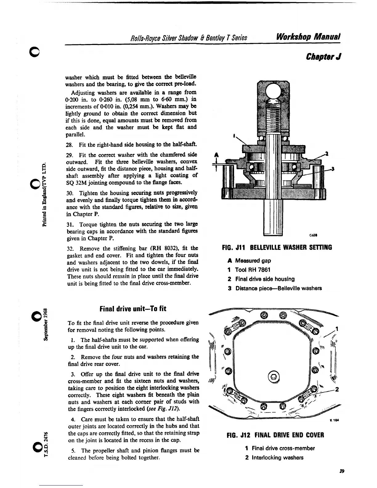
FIG.
J11
BELLEVILLE WASHER SETnNG
gasket and end cover. Fit and tighten the four nuts
and washers adjacent to the two dowels, if the final
A
Measured gap
drive unit is not being fitted to the car immediately.
1
Tool
RH
7861
These nuts should remain in place until the final drive
2
Final drive side housing
unit is being fitted to the final drive cross-member.
3
Distance piece--Belleville washers
Final
drive
unit-To fit
0".
1
To fit the final drive unit reverse the procedure given
3
for removal noting the following points.
a
1.
The half-shafts must be supported when offering
up the final drive unit to the car.
2.
Remove the four nuts and washers retaining
the
final drive rear cover.
3.
Offer up the final drive unit to the ha1 drive
cross-member and fit the sixteen nuts and washers,
taking care to position the eight interlocking washers
correctly. These eight washers fit beneath the plain
nuts and washers at each comer pair of studs with
the fingers correctly interlocked
(see
Fig.
512).
4.
Care must
be
taken to ensure that the half-shaft
outer joints are located correctly in the hubs and that
2
the caps are correctly fitted, so that the retaining strap
on the joint is located in the recess in the cap.
FIG.
512
FINAL DRIVE END COVER
0;
5.
The propeller shaft and pinion flanges must
be
1
Final drive cross-member
I-
cleaned before being bolted together.
2
Interlocking washers