Rolls-Royce Silver
Shadow
8
Bentley
T
Series
Workshop Manual
Chapter
K
22.
Disconnect the fuel feed pipe from the float
chambers.
23.
Cars from Car Serial Number SRH 8742 and
onwards.
Remove the weakening device pipes
24.
Disconnect the carburetter spill
F,;e
from the
float chambers.
25.
Remove the float chamber lids and floats keeping
them identified for their respective carburetters.
26.
Remove the nut securing the throttle damper (if
fitted) to its bracket; remove the damper.
27.
Remove the throttle spring.
28.
Completely remove the two pinch bolts securing
the levers to the
'A'
and
'B'
bank carburetter butterfly
valve spindles; remove the levers.
29.
Remove the nuts and washers securing both
carburetters to the 'Tee' piece; remove the carburetters
together with the throttle damper bracket (if fitted)
adjacent to
'A'
bank carburetter.
Carburetter-To dismantle
(see
Fig.
KI2)
1.
Thoroughly clean the outside of the carburetter.
Important
Parts from the two carburetters
should not be interchanged. To
prevent this, the parts as they are
removed from each carburetter,
should be placed in two boxes,
preferably marked
'A'
bank and
'B'
bank.
2.
Unscrew and remove the damper and washer
from the suction chamber lid.
3.
Remove the suction chamber retaining screws
and remove the chamber without tilting it.
4.
Remove the piston spring.
5.
Carefully lift out the piston and needle assembly;
empty the damper oil from the piston rod.
For carburetters fitted
with
a fixed needle carry out
Operation
6
(see
Fig.
K17).
6.
Remove the needle locking screw and withdraw
the needle from the piston. If it cannot easily be
removed, first tap the needle inwards then pull out-
wards. Do not bend the needle.
If excessive force is
required to remove the needle it should be discarded
and a new one fitted.
For carburetters fitted with a spring loaded needle
and
centralised jet carry out Operations
7
and
8
(see
Fig.
KI8).
7.
Remove the needle guide locking screw from the
piston and withdraw the needle assembly taking care
not to bend the needle.
8.
Withdraw the needle guide from the needle and
remove the spring.
Note
The flange collar pressed onto the jet
needle isire-set at the factory and must
not be disturbed.
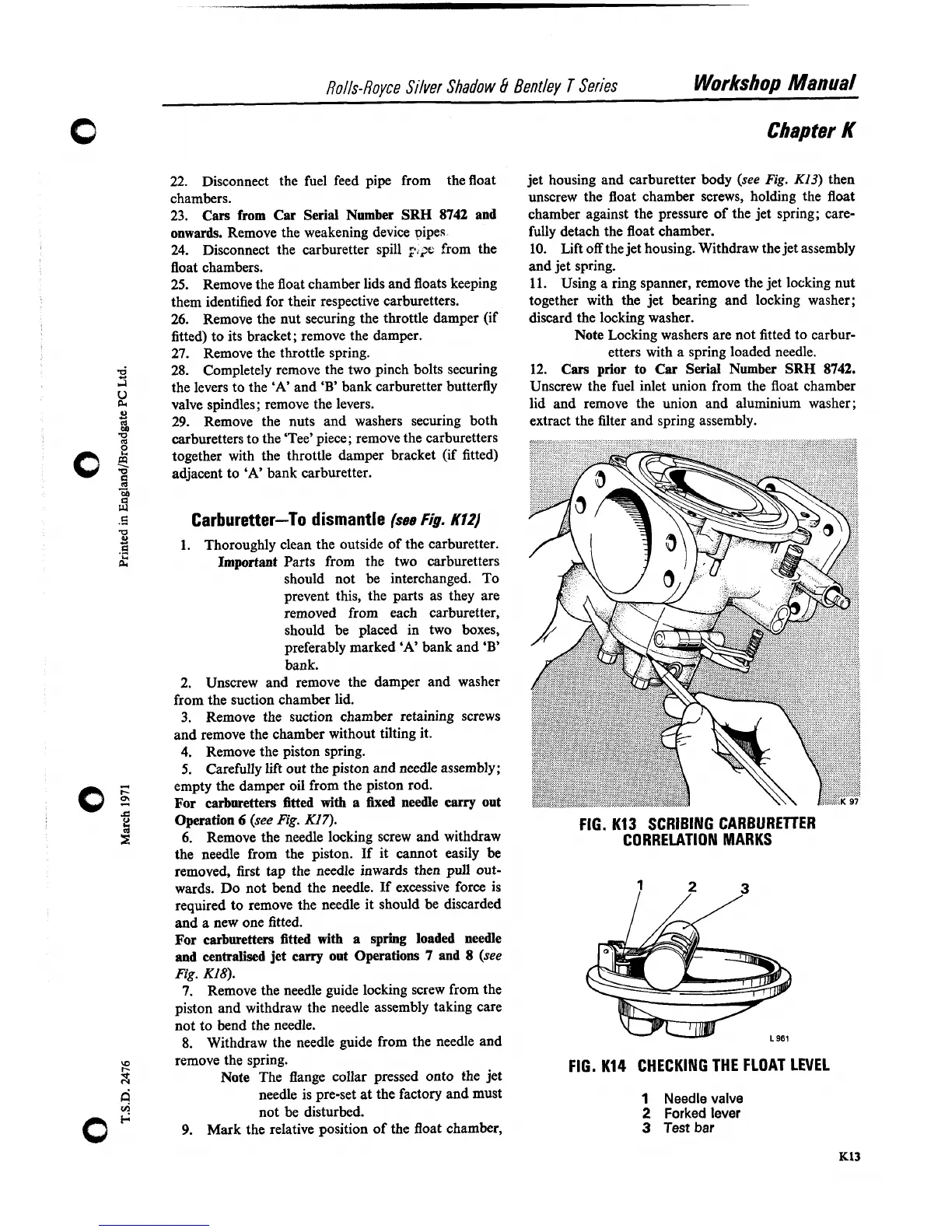
9.
Mark the relative position of the float chamber,
jet housing and carburetter body (see
Fig.
K13)
then
unscrew the float chamber screws, holding the float
chamber against the pressure of the jet spring; care-
fully detach the float chamber.
10.
Lift
off
the jet housing. Withdraw the jet assembly
and jet spring.
11.
Using a ring spanner, remove the jet locking nut
together with the jet bearing and locking washer;
discard the locking washer.
Note
Locking washers are not fitted to carbur-
etters with a spring loaded needle.
12.
Cars prior to Car Serial Number SRH 8742.
Unscrew the fuel inlet union from the float chamber
lid and remove the union and aluminium washer;
extract the filter and spring assembly.
FIG.
K13
SCRIBING CARBURETTER
CORRELATION MARKS
7
2
,
3
FIG.
K14
CHECKING
THE FLOAT LEVEL
1
Needle valve
2
Forked lever
3
Test
bar