Workshop
Manual
Rolls- Royce Silver Shadow
&
Bentley
T
Series
Chapter
M
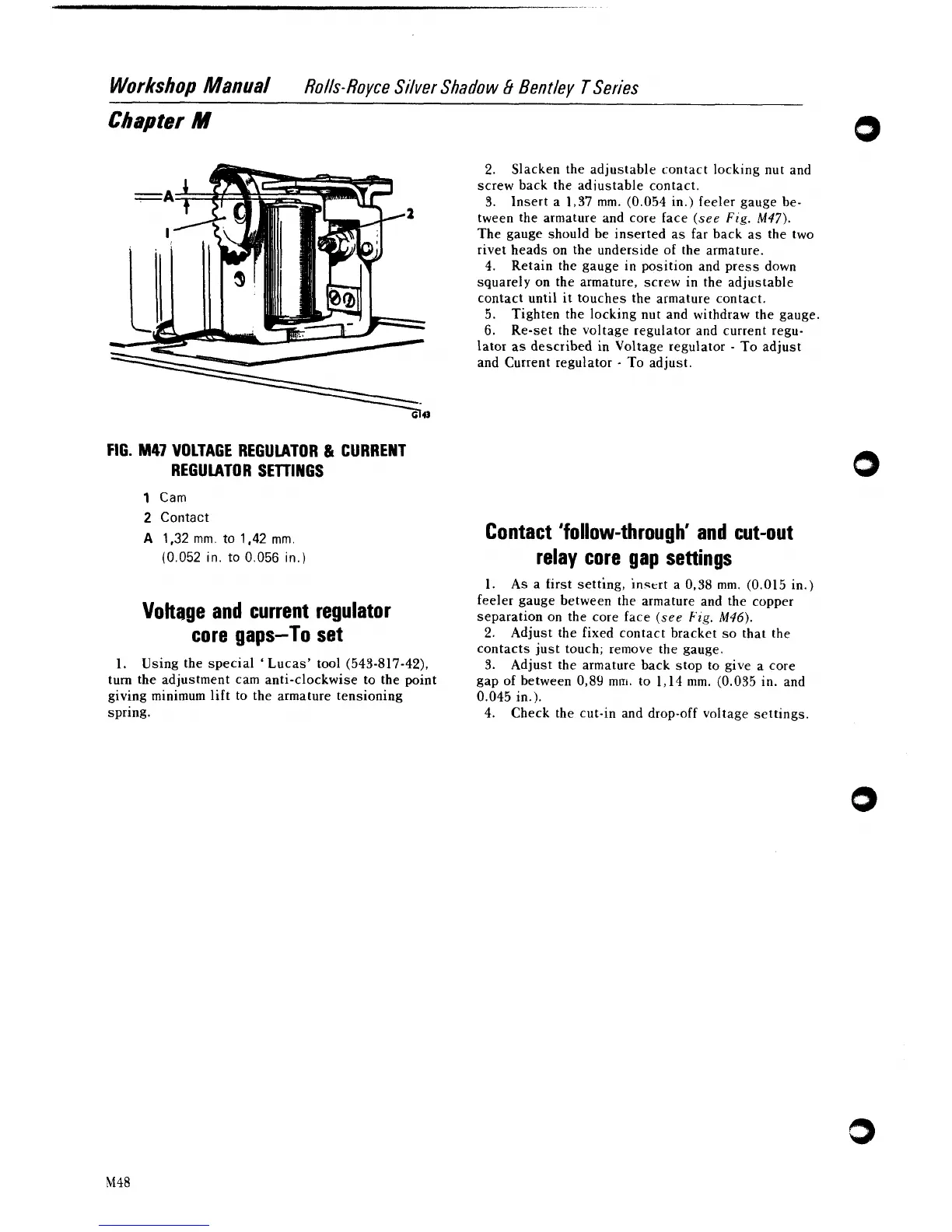
FIG.
M47
VOLTAGE REGULATOR
&
CURRENT
REGULATOR SETTINGS
1
Cam
2
Contact
A
1,32
mm.
to
1,42
mm.
(0.052
in.
to
0.056
in.)
Vohage and current regulator
core gaps-To set
1.
Using the special
'
Lucas' tool
(543-817-42),
turn the adjustment cam anti-clockwise to the point
giving minimum lift to the armature tensioning
spring.
2.
Slacken the adjustable contact locking nut and
screw back the adiustable contact.
3..
Insert a
1,37
mm.
(0.054
in.) feeler gauge be-
tween the armature and core face
(see
Fig.
M47).
The gauge should be inserted as far back as the two
rivet heads on the underside of the armature.
4.
Retain the gauge in position and press down
squarely on the armature, screw in the adjustable
contact until it touches the armature contact.
5.
Tighten the locking nut and withdraw the gauge.
6.
Re-set the voltage regulator and current regu-
lator as described in Voltage regulator
-
To adjust
and Current regulator
-
To adjust.
Contact 'follow-through' and cut-out
relay core gap settings
1.
As a tirst setting, insert a
0,38
mm.
(0.015
in.)
feeler gauge between the armature and the copper
separation on the core face
(see
Fig.
M46).
2.
Adjust the fixed contact bracket so that the
contacts just touch; remove the gauge.
3.
Adjust the armature back stop to give a core
gap of between
0,89
mm. to
1,14
mm.
(0.035
in. and
0.045
in.).
4.
Check the cut-in and drop-off voltage settings.