Workshop
Manual
Rolls h'oyce Silver Shadow
&
Bentley
T
Series
Chapter
J
5.
Remove the nuts and washers from the bearing
cap on each side of the crown wheel and differential
assembly (see
Fig.
J3).
6.
Remove the two bearing caps, and lift the crown
wheel and differential assembly from the casing.
Note (a) The crown wheel and differential
assembly cannot be lifted directly our of
the final drive casing, but must be re-
moved by lifting the crown wheel slightly,
then moved away from the pinion and
carefully past the pinion nose bearing
bridge.
(b) Precautions should be
taken during
Operation
5
to ensure that the two large
taper roller bearing tracks do not fall off,
as this could result in damage to the
rollers or tracks.
7.
Remove the four setscrews which secure the
pinion housing to the front flange of the casing and
insert
extractor screws into the two tapped holes in
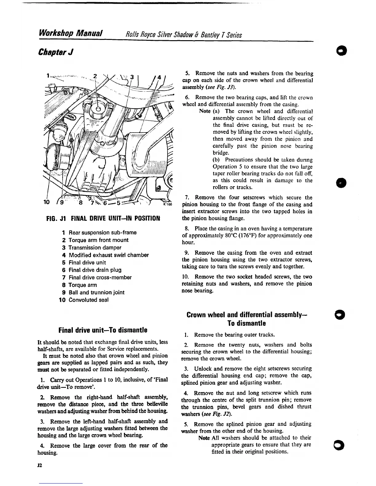
FIG.
J1
FINAL DRIVE UNIT-IN POSITION
the pinion housing flange.
8.
Place the casing in an oven having a temperature
1
Rear suspension sub-frame
of approximately 80°C
(176"F)for approximately one
2
Torque arm front mount
hour.
3
Transmission damper
4
Modified exhaust swirl chamber
9.
Remove the casing from the oven and extract
5
Final drive unit
the pinion housing using the two extractor screws,
taking care to turn the screws evenly and together.
6
Final drive drain plug
7
Final drive cross-member
8
Torque arm
9
Ball and trunnion joint
10
Convoluted seal
10. Remove the two socket headed screws, the two
retaining nuts and washers, and remove the pinion
nose bearing.
Crown wheel and differential assembly-
To dismantle
Final drive unit-To dismantle
1.
Remove the bearing outer tracks.
It should
be
noted that exchange final drive units, less
half-shafts, are available for Service replacements.
It must be noted also that crown wheel and pinion
gears
are supplied as lapped pairs and as such, they
must
not be separated or fitted independently.
1.
Carry
out Operations
1
to
10,
inclusive, of 'Final
drive unit-To remove'.
2.
Remove the right-hand half-shaft assembly,
remove the distance piece, and the
three belleville
washers and adjusting washer from behind the housing.
3.
Remove the left-hand half-shaft assembly and
remove the large adjusting washers
fitted
between the
housing and the large crown wheel bearing.
4.
Remove the large cover from the rear of the
housing.
2.
Remove the twenty nuts, washers and bolts
securing the crown wheel to the differential housing;
remove the crown wheel.
3.
Unlock
and remove the eight setscrews securing
the differential housing end cap; remove the cap,
splined pinion gear and adjusting washer.
4. Remove the nut and long setscrew which runs
through the centre of the split trunnion pin; remove
the trunnion pins, bevel gears and dished thrust
washers (see
Fig.
52).
5.
Remove the splined pinion gear and adjusting
washer from the other end of the housing.
Note
All wsshers should be attached to their
appropriate gears to ensure that they are
fitted in their original positions.