Rolls-Rovce Silver Shadow
&
Bentley
T
Series
Workshop
Manuel
8.
Place press tool
(see
Fig.
11!2,3)
so that the
spigot registe~s in the slip ring bore with the cut-
away portion in line with the field leads. Gently
press the slip-ring down until the press tool
spigot abutts the rotor shaft. Pass the field leads
through cut-away portion of press tool as they
appear.
9.
Trim off the ends of the glass-fibre sleeve
to leave approximately
+
inch projecting beyond the
rotor shaft. This will prevent the field leads from
shorting onto the shaft during service. Wrap the
field leads around the terminal posts of the slip
ring, cut to length, and solder in position.
10.
Mount the rotor in a suitable lathe, locating
the steady on the outer race of the SRE bearing.
Lightly skim the slip rings to ensure that they are
concentric with the SRE bearing to within
0,05
mm.
(0.002 in.). Remove the minimum amount of metal
to achieve this degree of concentricity and do not
0
reduce the slip ring diameter to below 28.85 mm.
(1.136 in.). To obtain the required surface finish,
it is essential that a highly finished diamond or
tungsten carbide tipped cutting tool be used for this
operation.
Electrical tests
1.
Subject the stator to an insulation test
between any terminal tag and the frame. The
minimum resistance should be 10 megohms.
2.
Connect the stator leads, two at a time to a
20
ampere dc supply and check that the voltage
drop in each case is
2.2
volts.
Chapter
M
Note:If any of the diodes have been replaced
or
if
the polyurethane paint (blue) on the
diodes is damaged the diodes must be
painted with polyurethane paint.
(Early cars only).
Diode replacement (SRE shield)
Note: Individual diodes cannot be replaced
and a fault in any diode will entail the
renewal of the complete associated heat
sink.
1.
Carefully separate the Ross Courtney tag
from the
'
A'
lead and pull the lead through the
rubber grommet in the end shield. Remove and
discard grommet.
2.
Remove external positive and negative main
terminal nuts, spring washers, terminal post
retaining nuts, spring and plain washers.
3.
Remove heat sink securing screws (two large
cheese headed screws), spring and plain washers
from underside of SRE shield. Withdraw complete
heat sink assembly.
4.
Snip the two copper braids of the faulty heat
sink close to the angle terminal tags and unsolder
the sleeved lead from the third diode. Remove
appropriate nylon retaining washers and withdraw
heat sink.
5.
Assemble new heat sink ensuring that nylon
insulating washers are interposed between adjacent
heat sinks. Replace outside retaining washers.
6.
Solder the diode braids to the appropriate
angle tags. (Note: the length of the braids are such
that it is impossible to connect them incorrectly).
7.
Solder sleeved wire to remaining diode.
Slipring end shield diode tests
0
Connect a test probe in series with a 48 watt 24
volt
lam$ on the positive terminal of
24
volt dc
supply. Connect another test probe to the negative
terminal of the dc supply.
Test Test lead
Test lead Diode under Serviceable
No. Connection
Connection test
1
(+I
(-1
840
1
Each heat sink
D
Positive Lamp
in turn illuminates
2
D
Each heat Positive No
sink in turn illumination
3
D-
Each heat Negative Lamp
sink in turn illuminates
4
Each heat sink
D-
Negative No
in turn illumination
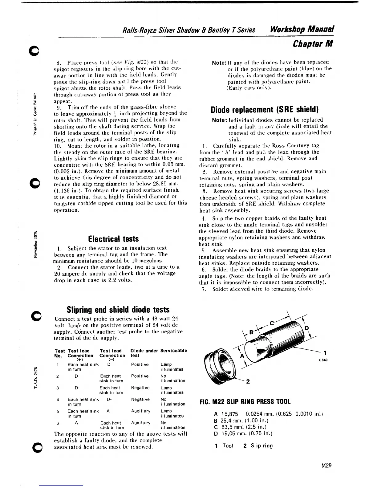
FIG.
M22
SLIP RING PRESS TOOL
5
Each heat sink
A
Auxiliary Lamp
in turn illuminates
A
15,875 0.0254
mm.
(0.625 0.0010
in;)
6
A
Each heat Auxiliary No
B
25,4
rnm.
(1.00
in.)
sink in turn illumination
C
63.5
mrn.
(2.5
in.)
The opposite reaction to any of the above tests will
D
19,05
rnm.
(0.75
in.)
establish a faulty diode, and the complete
0
associated heat sink must be renewed.
1
Tool
2
Slip
ring