Rolls-Royce Silver Shadow
6
Bentley
T
Series
Workshop
Manual
I. Thoroughly clean all components before assem-
Half-shaft-T~
fit
bly.
2.
When assembling the Hardy Spicer universal
joint onto the half-shaft, the needle roller bearings
should
be
fitted in the retainers and smeared with
Retinax A grease (see under 'Hardy Spicer joint-
To fit').
Note It is important not to pack too much
grease on the rollers or in the retainers
as this could result in damage to the lip
seals on assembly.
3.
Assemble the trunnion bearings, and buttons
onto the trunnion pin, but at this stage do not fit the
adjusting washers under the trunnion button heads.
4.
Using a micrometer, carefully measure the
dimension over the trunnion buttons.
5. Measure the dimension between the outer cir-
cumferences of the two outer bores in the joint
housing in which the buttons locate.
6.
The difference between these two dimensions
gives the amount which must
be
taken up by adjust-
ment, but it is
essential
that this figure is divided by
two and washers of equal thickness fitted under each
button.
7.
The adjustment should
be
carried out by fitting
shim
washers under the trunnion buttons to obtain
a
fit of 0.0005 in. (0,013
mm.)
tight to 0.0005
in.
(0,013
mm.)
slack
in
the joint housing.
Shim
washers are available for this purpose in a
8
range from 0.012 in. to 0.023 in. (0,304
rnm.
to 0,584
#
mm.)
in 0.001 in. (0,025
mm.)
increments.
8.
Fit the correctly adjusted trunnion assembly into
the joint body then ease the neoprene seal over the
body and tighten the two seal clips, ensuring that the
small end of the seal is located correctly on to the
machined diameter of the half-shaft.
Note When the half-shaft has been fitted to
the car the seal should be inspected, whilst
the car is at its normal standing height,
to ensure that the seal convolutions are
not 'crimped' or strained. If they are,
the position of the seal on the half-shaft
should be adjusted slightly to correct this.
9.
Remove the drain plug from the joint housing
m
and inject 150
C.C.
of
S.A.E.
90
EP
oil into the joint
and refit the plug.
10.
Fit the half-shaft as instructed under 'Half-shaft
6
-To
fit'.
Fit the half-shaft by reversing the procedure given
for removal, noting the following points.
1.
If
an exchange shaft is being fitted, this is supplied
suitably blanked and protected.
Remove the pro-
tective covering from the joint body splines and also
remove the cover on the breather hole in the end of
the
splined shaft.
All
traces of protective material
must
be
removed.
2.
Remove the drain plug from the joint body and
inject 150
C.C.
of S.A.E. 90
EP
oil into the joint;
fit
the plug.
3.
Remove the circlip and washer from behind the
bearing housing on the old shaft and fit the housing,
washer and
circlip to the new shaft.
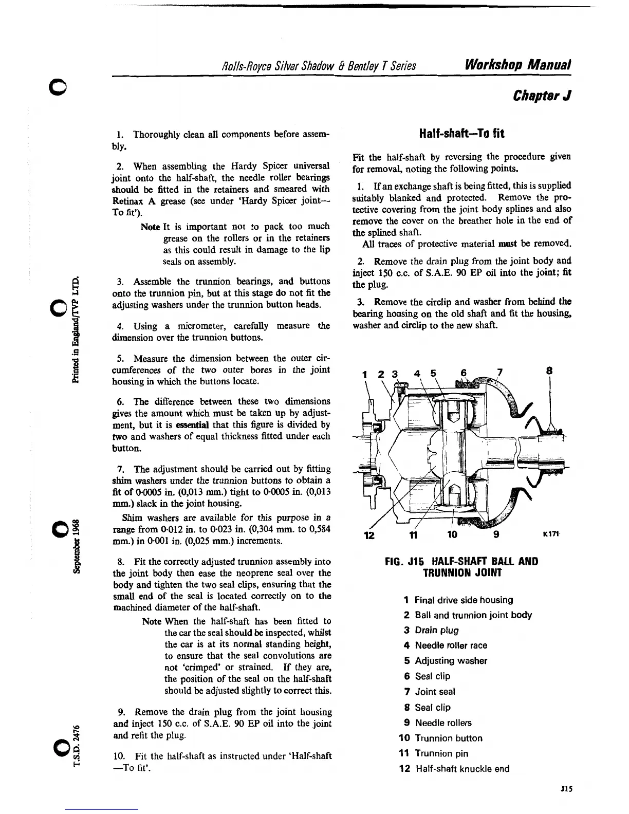
FIG. 515
HALF-SHAFT BALL AND
TRUNNION JOINT
1
Final drive side housing
2
Ball and trunnion joint body
3
Drain plug
4
Needle roller race
5
Adjusting washer
6
Seal clip
7
Joint seal
8
Seal clip
9
Needle rollers
10
Trunnion button
11
Trunnion pin
12
Half-shaft knuckle end