Rolls-Royce Silver Shadow
&
Bentley
T
Series
Workshop
Manual
Testing in position
1.
Check and if necessary adjust the generator
driving belts (see Chapter
L).
2.
Disconnect the generator (dynamo) leads at the
control unit terminals marked 'D' and
'
F'.
3.
Connect the two leads to the positive terminals
of a Zero to
20
Volts voltmeter. Connect the
negative lead to a good earthing point.
4.
Start the engine but do not allow the generator
speed to exceed
1000
r.p.m.
5.
If the generator attains normal voltage, check
the
'
RB
340'
control unit, the wiring and the battery
connections.
1
2
3
4
Chapter
M
Section
M6
GENERATOR
6.
If there is no voltage build-up, remove the
generator (see Generator
-
To
remove) and examine
the condition of the brushes and commutator.
7.
Hold back each brush spring in turn and move
the brush by gently pulling on its flexible connector
(see
Fig.
M39). If the movement is sluggish, remove
the brush from its box and ease the sides of the
brush by lightly polishing on a smooth file. Clean
out the brush boxes if dirty and check the
clearances of the brushes in the boxes as sticking
of the brushes can occur if clearances are
insufficient (see
Fig.
M40). It is important that the
brushes are fitted in their original positions.
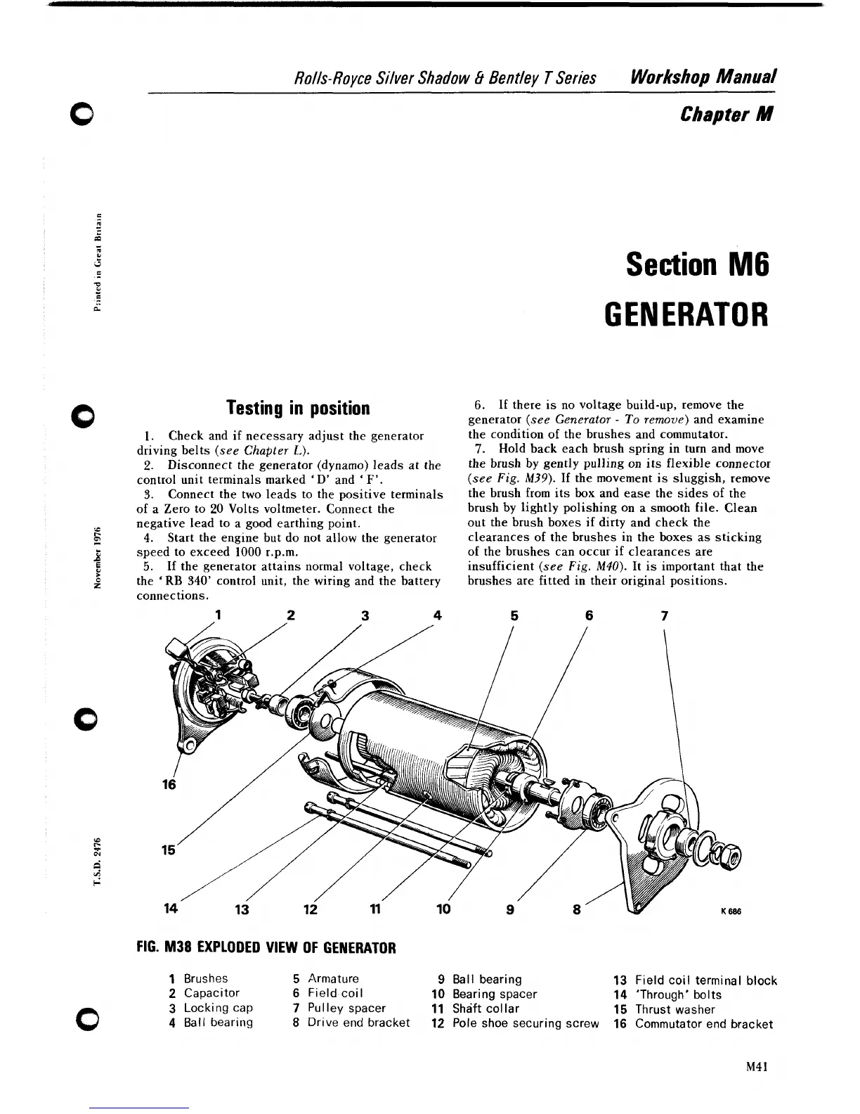
FIG.
M38
EXPLODED
VIEW
OF GENERATOR
1
Brushes
5
Armature
9
Ball bearing
13
Field coil terminal block
2
Capacitor
6
Field coil
10
Bearing spacer
14
'Through' bolts
3
Locking
cap
7
Pulley spacer
11
Shaft collar
15
Thrust washer
4
Ball bearing
8
Drive end bracket
12
Pole shoe securing screw
16
Commutator end bracket