Rolls-Royce Silver
Shadow
8
Bentley
T
Seri~s
Workshop Manual
Chapter
K
Fuel evaporation loss control canister-
To remove
The canister is mounted under the left-hand front
wing and is removed as follows.
1. Remove the front left-hand road wheel as des-
cribed in Chapter R-Wheel-To remove.
Note Left-hand front is determined when
viewed from the driver's seat.
2.
Suitably position stands under the raised portion
of the car as a safety
precuation.
3.
Remove the front section of the underwing sheet
by unscrewing the
6
in.
A/F
nut and bolt, and the
16
small screws situated around the sheet.
4.
The canister is now clearly visible.
5.
Using special pliers (RH8090), remove the steel
retaining clips and detach the four rubber hoses con-
nected to the canister.
6.
Raise the bonnet.
7.
Inside the engine compartment adjacent to the
blower motor resistances, (see
Fig.
K40)
locate the
six
6
in.
A/F
setscrews. Unscrew the lower four set-
screws and withdraw the canister from beneath the
wing.
Fuel evaporation loss control canister-
To fit
Fit the canister by reversing the procedure described
for removal, noting the following points.
1. Ensure that the rubber hoses are
in
a good con-
dition and new hose retaining clips are used.
2.
Ensure that the underwing sheet is sealed with
Bostik Sealing Compound 771.
Purge line
(see
Fig.
K39)
The purge line consists of a rubber hose, passing from
the lowest connection on the canister through the
valance junction piece to the gulp air pipe situated
between the gulp valve and carburetter 'Tee' piece.
Incorporated into this hose there is the purge line filter
and restrictor.
When the engine is running, air drawn through the
canister fitter and carbon picks up the stored fuel
vapours and passes them via the hose, to the induction
manifold. The restrictor in the line controls the flow
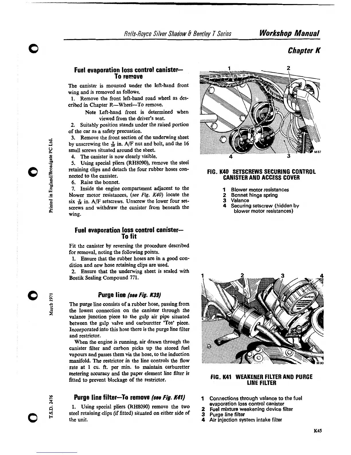
FIG. K40 SETSCREWS SECURING CONTROL
CANISTER AND ACCESS COVER
I
Blower motor resistances
2
Bonnet hinge spring
3
Valance
4
Securing setscrew (hidden
by
blower motor resistances)
rate at
1
cu.
ft.
per min. to maintain carburetter
metering accuracy and the paper element line filter is
fitted to prevent blockage of the restrictor.
FIG.
K41
WEAKENER FILTER AND PURGE
LINE FILTER
Purge line filter-TO remove
(sse
Fig.
K41)
1
Connections through valance to the fuel
evaporation loss control canister
1.
Using special pliers (RH8090) remove the two
Fuel
mixture
weakening
device
filter
steel retaining clips (if fitted) situated on either side of
3
Purge
line
filter
the unit.
4
Air
injection system intake filter