Servicing and cleaning
76 / 97
Inspection procedures
Fuses and relays
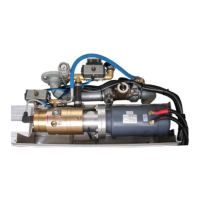
The electrical circuits on the electrical unit of the portable fire pump are se-
cured with fuses.
The fuse holder is located on the side away from the operator, behind the
air filter box
The fuse holder is located on the side opposite the operator, behind the air
filter box
Before replacing the burnt out fuse, check the cause of the defect. Do not
repair defective fuses and relays - fire risk. Only use prescribed fuses and
relays.
Fuse allocation:
• F1-5 10A control
• F1-3 15A cooling fan
• F130 0.05A tank illumination
• F3-5 20 A main fuse
• F3-3 10A operation
• F3-1 10A charge
Relay allocation:
• K319 cooling fan relay
• K8 main relay
• KRLS RLS relay
Fuse allocation