4 CHAPTER 4 - PRODUCT DESCRIPTION
All models have been designed to lift motor-vehicles at any level between the minimum and
maximum height.
The maximum lifting weight, including any additional load on the vehicle, is as specified on the
serial plate.
All mechanical frames, such as platforms, extensions, base frames and arms have been built in a
pressure bend plant to make the frame rigid and strong while keeping a low weight
The electro hydraulic operation is described in detail in chapter 8
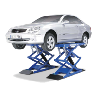
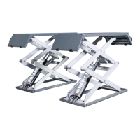
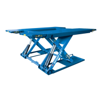
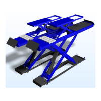
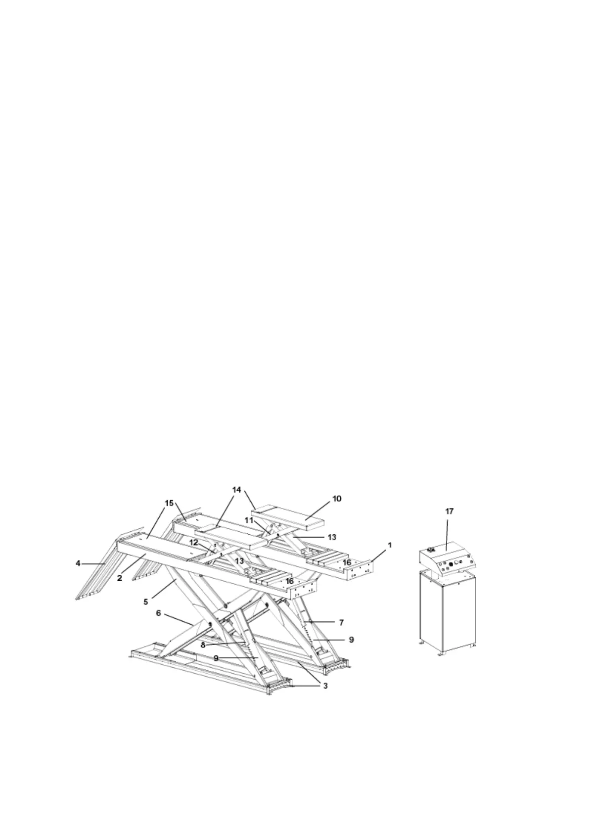
As shown in figure 3, the lifts is composed of two platforms, the platform 1 (1) and the platform 2
(2) anchored to the ground by means of two base frames (3)
The lift is equipped with 4 drive-up ramps (4) at the end of the platforms to facilitate the entry the
of vehicle.
Platforms, linked to the base frame by means of a scissors lifting system, is 4200 mm in length and
the lifting system of each platform is composed of two arms, external (5) and internal (6), as well
as a cylinder primary (7)in platform P1, and a secondary cylinder (8) in platform P2.
On both cylinders are installed mechanical safety devices. (9).
Lift lowering and lifting are carried out by means of a control box (17) (fixed to the ground) next
to the lift.
Models LT and LTAT, are equipped with an auxiliary lift or lift-table,(10) for further lifting of the
vehicle. Two cylinders (11) for platform P1 and (12) for platform P2 raise the auxiliary lift.
On both cylinders are installed mechanical safety devices. (13).
Auxiliary lift platforms are equipped with extensions. (14).
Models LT e LTAT are equipped with slip plates (15) and recess for turn plates (16).
 Loading...