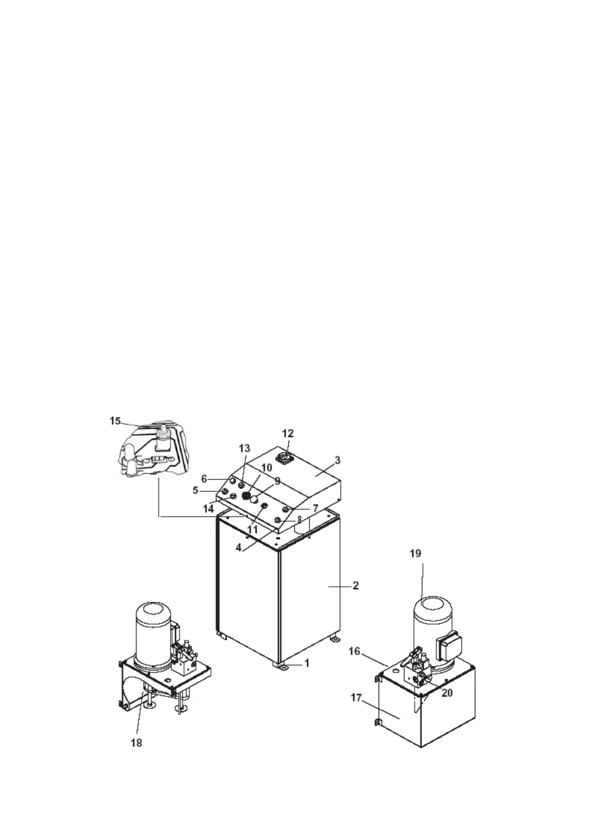
The Control desk is composed of a frame (1) covered with panels (2) and a top panel (3).
The control panel (4) is placed on the front of the top panel and is equipped with:
Double function button:
Mechanical safety insertion / final lowering (last 400 mm.) (5)
Pilot lamp (6)
Up push button (7)
Down push button (8)
Emergency button (9)
Beeper (10)
0/1 Selector (lift / auxiliary lift) only models “LT” e “LTAT” (11)
Whenever the lift is equipped with play detectors the selector ( 11) has 3 positions
Main switch (12)
1
st
working position push button (13)
2
nd
working position push button (14)
The limit switches (height limit stop runway, height limit stop lift-table and runway photocell)
override button (15) is placed inside the control desk, under the electric panel..
The hydraulic unit is made of : oil tank (17), hydraulic pump (18) electric motor (19), solenoid
valve (20) and hydraulic hoses.
 Loading...