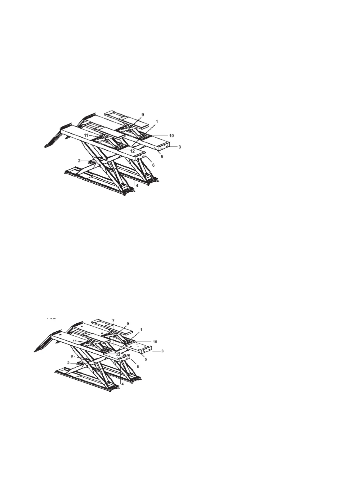
(1) The proximity switch is placed between P1
Platform scissors to stop the lift at the
safety height (400 mm);
(2) the proximity switch is placed between P2
platform scissors to stop the lift at the
maximum height
(3) The leveling system limit switch for platform
P1 is under the runway on left external side.
(4) The leveling system limit switch for platform
P2 is under the runway on right external side.
(5) The photocell is locate don internal side of
platform P1.
(6) The reflector is located in the internal side of
platform P2
(9) Safety height (130 mm) for auxiliary lift sensor
is installed on arms of platform P1
(10) Auxiliary lift platform P1 leveling sensor, is
installed on of auxiliary lift platform P1 base
frame;
(11) Auxiliary lift maximum height limit switch, is
installed on of auxiliary lift external arm P2;
(12) Auxiliary lift platform P2 leveling sensor, is
installed on of auxiliary lift platform P2 base
frame;
(1) The proximity switch is placed between P1
Platform scissors to stop the lift at the
safety height (400 mm);
(2) the proximity switch is placed between P2
platform scissors to stop the lift at the
maximum height
(3) The leveling system limit switch for platform P1 is
under the runway on left external side.
(4) The leveling system limit switch for platform P2 is
under the runway on right external side.
(5) The photocell is locate don internal side of platform
P1.
(6) The reflector is located in the internal side of platform
P2
(7) Limit switch for 1
st
working position is located on
internal arm of platform P1
(8) Limit switch for 2
nd
working position is located on
internal arm of platform P2
(9) Safety height (130 mm) for auxiliary lift sensor is
installed on arms of platform P1
(10) Auxiliary lift platform P1 leveling sensor, is installed
on of auxiliary lift platform P1 base frame;
(11) Auxiliary lift maximum height limit switch, is
installed on of auxiliary lift external arm P2;
(12) Auxiliary lift platform P2 leveling sensor, is installed
on of auxiliary lift platform P2 base frame
 Loading...