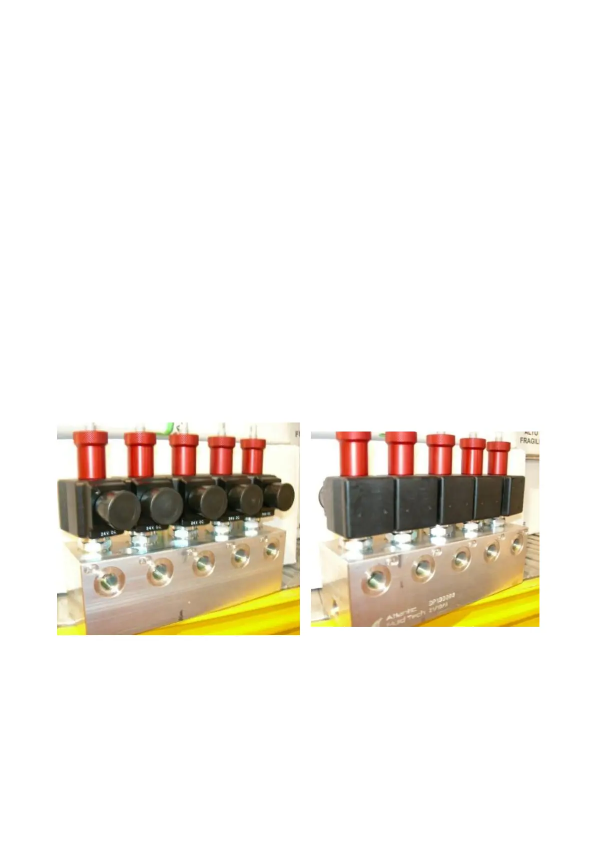
“LT” and “LTAT” models are equipped with aluminium block on which are installed :
(1) auxiliary lift leveling solenoid valve (EV 8)
(2) auxiliary lift switching solenoid valve (EV 6)
(3) platform lowering solenoid valve (EV 3)
(4) auxiliary lift lowering solenoid valve (EV 7)
(5) platform leveling solenoid valve (EV 2)
(6) platform switching solenoid valve (EV 4)
(7) max pressure valve
(8) check valve
(9) platform lowering control valve
(10) auxiliary lift manual lowering valve
(11) auxiliary lift max pressure valve
(12) hand pump
Pressure gauges connections A1 and C1 are located on hydraulic block side , for both the
platform and the auxiliary lift.
 Loading...