INSTRUCTION, USE AND
MAINTENANCE MANUAL
GB
Page 15 of 57
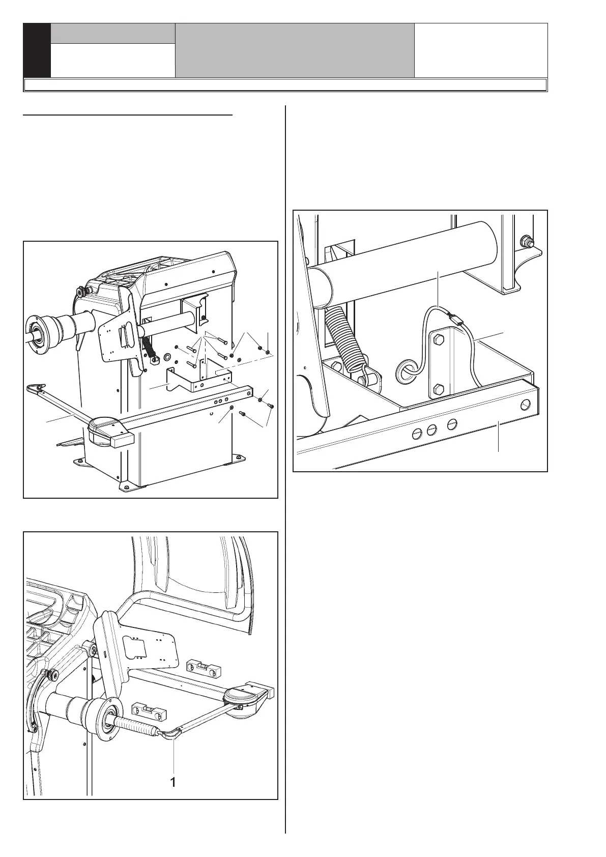
9.3.3 Fitting of external data gauge
1. Introduce the 4 screws (Fig. 8 ref. 1) in the gauge
bracket (Fig. 8 ref. 2) and screw them on the
threaded rivets placed on the rear side of the frame.
Lock the gauge arm (Fig. 8 ref. 3) to the bracket
(Fig. 8 ref. 2) using the 2 screws (Fig. 8 ref. 4) and
the washers (Fig. 8 ref. 5). Lock the screws (Fig. 8
ref. 4) with the washers (Fig. 8 ref. 5) and the nuts
(Fig. 8 ref. 6) so that the shaft and the gauge arm
are levelled out (see Fig. 9).
1
2
3
4
5
5
6
5
Fig. 8
2. Also make sure the gauge tip (Fig. 9 ref. 1) is po-
sitioned at the centre of the mandrel.
Fig. 9
3. Connect connector (Fig. 10 ref. 1) of the cable com-
ing from inside the machine to connector (Fig. 10
ref. 2) of the cable coming from the gauge arm. Fit
the section of the cable with the connectors inside
the arm (Fig. 10 ref. 3).
4. Fasten the cable with clamps.
5. Enable the external data gauge and carry out the
device's calibration.
1
2
3
Fig. 10
1297-M008-8
 Loading...