d04925.fm
INSTALLATION MANUAL
BRP-Powertrain
Effectivity: 912 Series
Edition 2/Rev. 0
76-00-00
page 9
August 01/2012
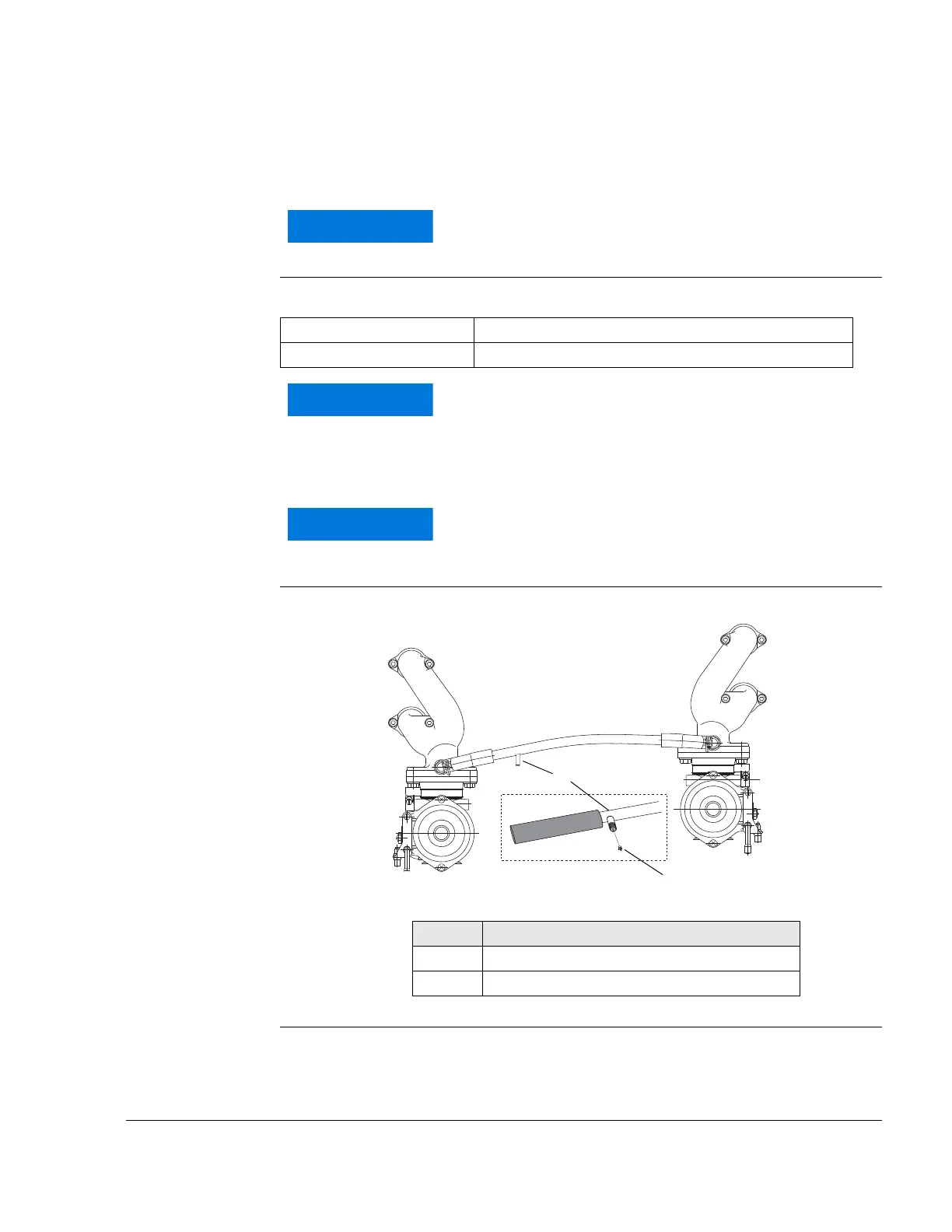
2) Monitoring of the intake manifold pressure
General note See Fig. 5.
Connection nip-
ple
Connection nipple (1) to measure manifold pressure:
Graphic Monitoring of the intake manifold pressure
Fig. 5
02051
Utilize the total slip-on length on all joints. Secure hose
by suitable screw clamps or crimp connection.
Outside dia. 6 mm (1/4“)
Slip-on length Max. 17 mm (11/16“)
Protective covering to be utilized for transport and at
engine installation only. If connection for pressure
reading is not employed it has to suitably plugged. New
style compensating tubes have plugged this connec-
tion by a screw M3.5x6 (2).
Flawless operation of the indicating instrument needs
the installations of a water trap between engine and in-
strument for fuel condensate.
Part Function
1 Connection nipple
2 Screw M3.5x6
 Loading...