d04921.fm
INSTALLATION MANUAL
BRP-Powertrain
Effectivity: 912 Series
Edition 2/Rev. 0
61-00-00
page 7
August 01/2012
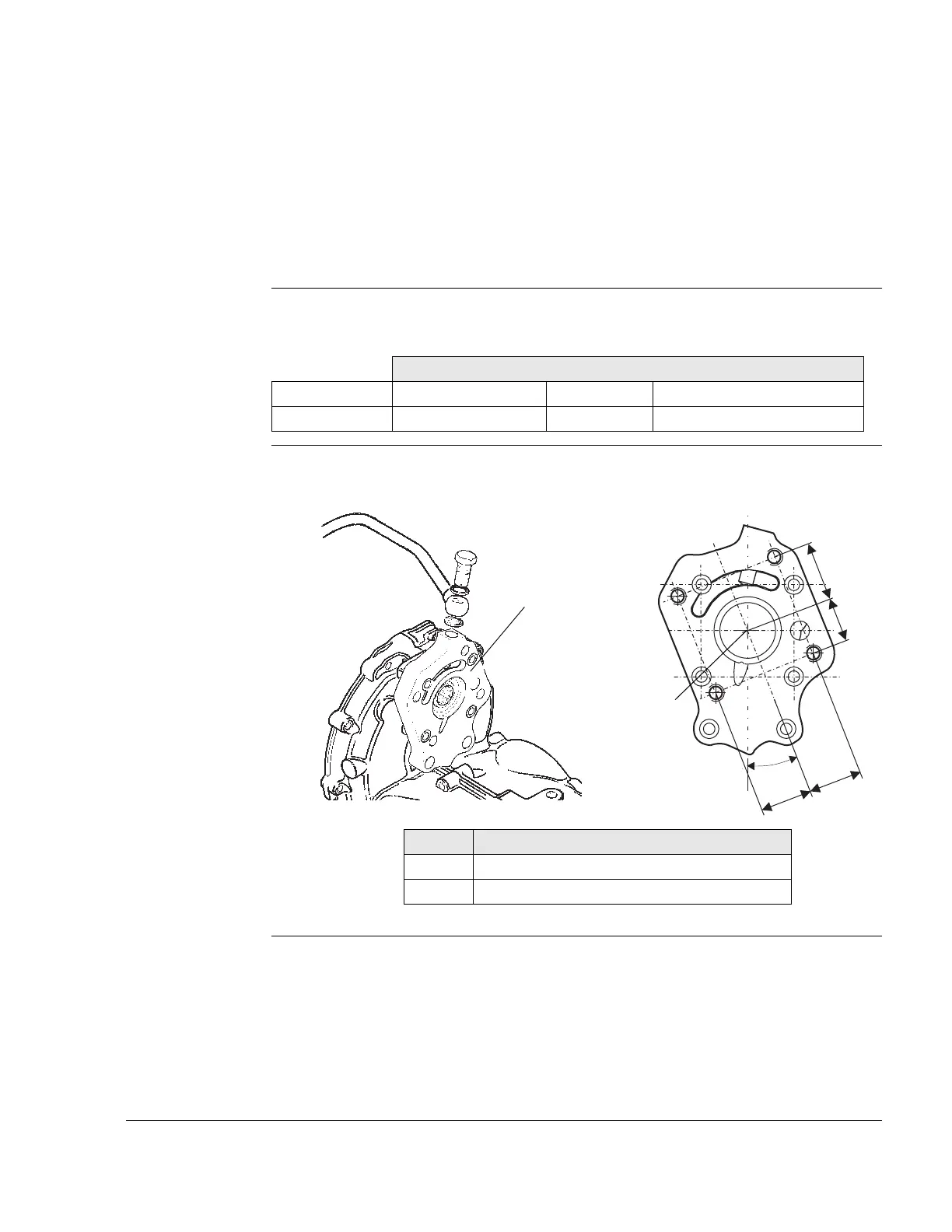
3) Hydraulic governor for constant speed propeller
3.1) Technical data for connections
General note See Fig. 5.
NOTE: See therefore also SB-912-052 “Installation/Use of gover-
nors for ROTAX engine type 912 and 914“, latest issue.
Drive Drive via propeller gearbox.
- Position of the propeller connection (1) on the governor flange
Graphic Crankcase flange
Fig. 5
00256,08179
Axes
Point of support x-Axis mm y-Axis mm z-Axis mm
-206.3 mm (-8.12 in.) 0 51.5 mm (2.03 in.)
Part Function
1 Connection for hydraulic governor
2 Governor flange
 Loading...