d04922.fm
INSTALLATION MANUAL
BRP-Powertrain
Effectivity: 912 Series
Edition 2/Rev. 0
72-00-00
page 3
August 01/2012
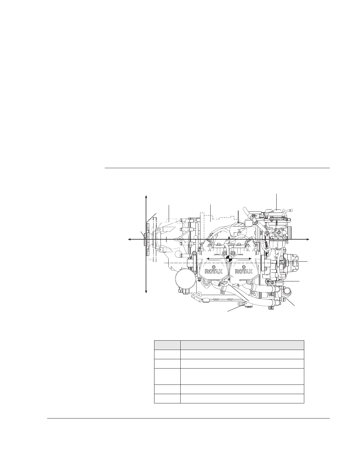
1) Engine components, engine views, cylinder designation
General note See Fig. 2.
PTO power take off side
MS magneto side
A points of attachment (for engine transport) - centre of gravity
P zero reference point for all dimensions
NOTE: Allow ± 1 mm on all stated dimensions as manufacturing
tolerance.
x, y, z axes for system of coordinates
Cyl. 1 Cylinder 1 Cyl. 3 Cylinder 3
Cyl. 2 Cylinder 2 Cyl. 4 Cylinder 4
Side view
Part Function
1 Propeller flange
2 Propeller gear
3 Vacuum pump or hydraulic governor for con-
stant speed propeller
4 Constant depression carb
5 Ignition cover
+z
-z
+x
-x
P
AS
MS
A
+z1
-x1
+x1
-z1
 Loading...