A4US
US
A4
US A4
US
A4
A4 US
US
A4
US
A4
A4 US
5 Preparing the Drive Bush
5.1 Drive Bush - Type A Coupling:
Please see Publication PUB111-001 for thrust/torque
allowances.
(Note: CK30/60 actuators may be fitted with a F07/FA07
flange adaptor, in which case this will need to be removed
before the below procedure is carried out).
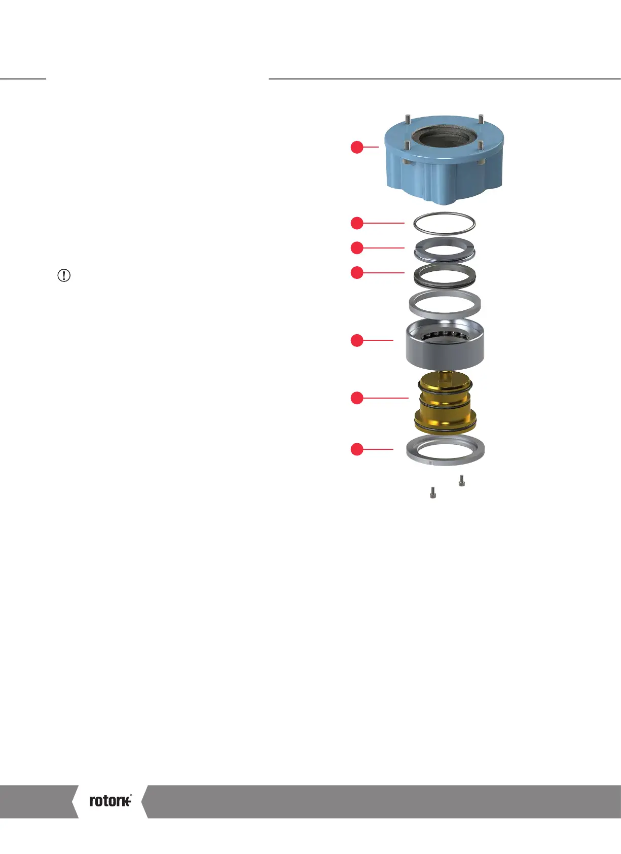
Turn the actuator onto its side, removing the hex head screws
holding the thrust base (1) onto the actuator.
Remove the two M3 cap screws retaining the spigot ring (2)
Pull out the drive bush (3) complete with the bearing
assembly (4)
CAUTION: Failure to remove the bearing assembly
and the o-rings prior to machining may result in damage
to the bearing.
5.1.1 Disassembly of bearing assembly
Locate and remove the snap ring (5) using a suitable tool
Remove the split collar (6)
If fitted, remove the spacer ring (7)
Slide the bearing (4) off the drive bush (3)
Keep the bearing and the drive bush components clean.
The split collar keys (6) must be kept as a machined pair.
Machine the drive bush, after removing the o-rings, allowing
clearance for rising spindle applications.
5.1.2 Reassembly of bearing assembly
Ensure the drive bush (3) is clean and free from swarf. Ensure
the o-rings are clean and greased (see Section 11 for typical
grease). Slide the bearing assembly (4) onto the drive bush (3)
and ensure that it is fitted down to the shoulder. Grease and
refit the split collar keys (6) and spacer ring (7) if fitted and
secure with the snap ring (5).
Grease and refit the drive bush bearing assembly into the
thrust base.
Refit the thrust base (1) ensuring that the drive dogs on the
bush align with the slots in the hollow center column and
secure with the hex head screws to the following torque
values: See Table A on page 13.
1
5
6
7
4
2
3
CK Range Safe Use and Installation Manual
10
 Loading...


