A4US
US
A4
US A4
US
A4
A4 US
US
A4
US
A4
A4 US
A4US
US
A4
US A4
US
A4
A4 US
US
A4
US
A4
A4 US
6 Mounting the Actuator
6.2 Mounting the Actuator -
Rising Stem Valves
6. 2.1 Fitting the actuator and base as a combined unit
- all sizes
Fit the machine drive bush as described in Section 5.1 into the
thrust base assembly.
Lower the actuator onto the thxreaded valve stem, engage
HAND operation and wind the handwheel in the open
direction to engage the drive bush onto the valve stem.
Continue winding the handwheel until the actuator is firmly
down on the valve flange. Continue winding for a further
two turns and secure with bolts, tightening down to the listed
torques - Table A.
6.2.2 Fitting thrust base to valve - all sizes
Fit the machine drive bush as described in Section 5.1 into the
thrust base assembly.
Remove the thrust base as described in Section 5.1 and place
it on the threaded valve spindle with the drive keys pointing
uppermost and turn the thrust base in the open direction to
engage it on the spindle. Continue turning until the thrust
base is on the valve flange but do not tighten at this stage.
Lower the actuator onto the thrust base and rotate the
complete actuator until the drive keys on the drive bush align
with the slots on the base of the center column. Continue to
turn the actuator until the fixings holes align with the thrust
base. Replace the base bolts and tighten to the required
torque - Table A.
Open the valve by two turns and secure the thrust base to the
valve flange and tighten to the required torque - Table A.
6.3 Mounting the Actuator -
Non Rising Stem Valves - Top Mounted
Ensuring that that the drive bush fits the input shaft/key and
has adequate axial engagement then fit into the actuator as
described in Section 5.1/5.2
Engage HAND, offer up the actuator to the valve, turning
the handwheel to align the drive bush. Tighten the mounting
bolts to the required torque - Table A.
Note: When the thrust is being taken in the actuator, a
thrust nut must be fitted above the drive bush and securely
tightened.
6.4 Mounting the Actuator -
Valve with Gearbox - Side Mounted
Follow the instructions in Section 6.3 as for top mounted
instructions, checking that the mounting flange is at right
angles to the shaft before installation.
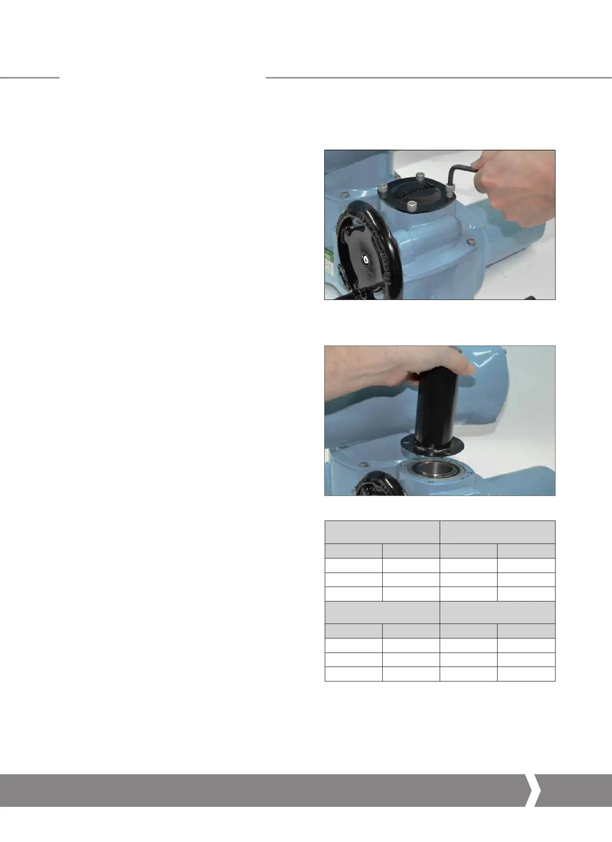
6.5 Actuator Sealing
Ensure that the sealing cap and o-ring assembly is securely fitted
to prevent moisture ingress into the centre column of the actuator.
For valves with rising spindles, a cover tube may be fitted.
Ensure that the o-ring is correctly fitted and that the cover
tube is secured with the supplied fasteners.
Metric Torque
Flange Fixing Nm lbf.ft
F07 M8 26.1 19.3
F10 M10 51.6 38
F14 M16 219.8 162.1
Imperial Torque
Flange Fixing Nm lbf.ft
FA07 5/16 24.3 17.9
FA10 3/8 42.3 31.2
FA14 5/8 205.3 151.4
Table A: Required Torque
Keeping the World Flowing
13
 Loading...


