Keeping the World Flowing
11
11.0 Removal from Valve
The End user is in charge of removing the actuator
from the valve.
Removal shall be performed only by qualified staff,
wearing/using appropriate personal protection devices.
Do not remove the actuator if the valve is blocked in
the intermediate position. Contact Rotork Fluid Systems
Customer Service.
To disassemble the actuator from the valve, proceed as
follows:
•
Cut off electrical power supply
•
Cut off pneumatic/hydraulic supply
•
Release any pressure from the control group
•
Remove the supply pipes from the actuator
•
Remove control and signal lines from electric
components (if any)
•
Sling the actuator in line with the instructions given in
Lifting Instructions
, page 7
•
Unscrew bolts or nuts from the stud bolts fixing the
actuator to the valve
•
Lift and remove the actuator from the valve
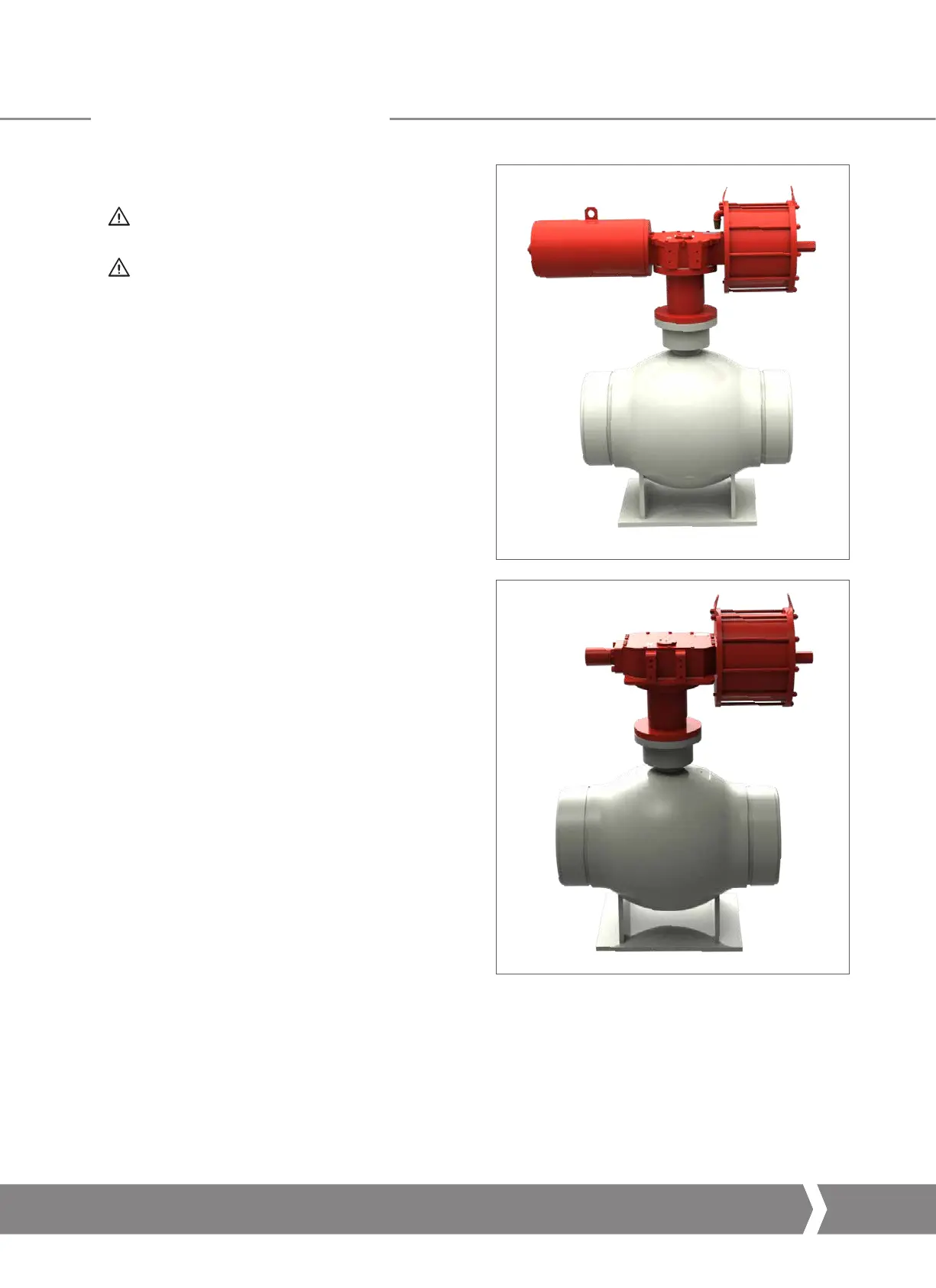
Fig 11.1 Actuator/valve assembling example
A4 US
US
A4
US
A4
A4 US
 Loading...