Profibus DP Mk2 Option Card Installation Manual
28 of 84 Publication PUB088-005-00_1017
Data line 1B is positive with respect to data line 1A when the PFU is transmitting a ‘1’.
Data line A is also called TxD/RxD-N
Data line B is also called TxD/RxD-P
If an analogue input is being used it is connected to the analogue input terminals. The Profibus card
caters for both current and voltage analogue signals. There is no power supply on the card for the
analogue transmitter and an external power supply must be used to power it.
For voltage inputs connect I/P A to the positive signal and analogue Common to the
negative signal from the transmitter
For current inputs connect I/P A to I/P B (to insert the conditioning resistor). The current
input positive is to I/P A and I/P B whilst the current input negative is connected to the
analogue Common.
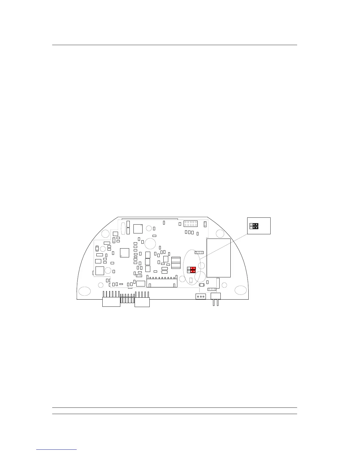
Active termination resistors are included on the Profibus card. The jumper links LK1 and LK2 on the
PNIC board are used to select the inclusion of these resistors.
Fit LK1 and LK2 as shown to provide pull apart active termination to the network at this
actuator and
Link Terminals ‘Terminator’ and ‘Profibus A Out’ to add end of line termination