Setting Up a Card
Publication PUB088-005-00_1017 77 of 84
8 SETTING UP AND MAINTAINING THE PROFIBUS MODULE
In most applications the majority of the default settings in the Profibus DP Module (Mk2) will be
suitable for the operation of the valve and need not be altered. However, in every case it will be
necessary to alter the address, since the default should never be used within a live system (the default
value is 126).
8.1 Using a Network Configuration Tool
The Profibus DP Module caters for two configuration tools, FDT and PDM.
8.1.1 FDT (Field Device Tool)
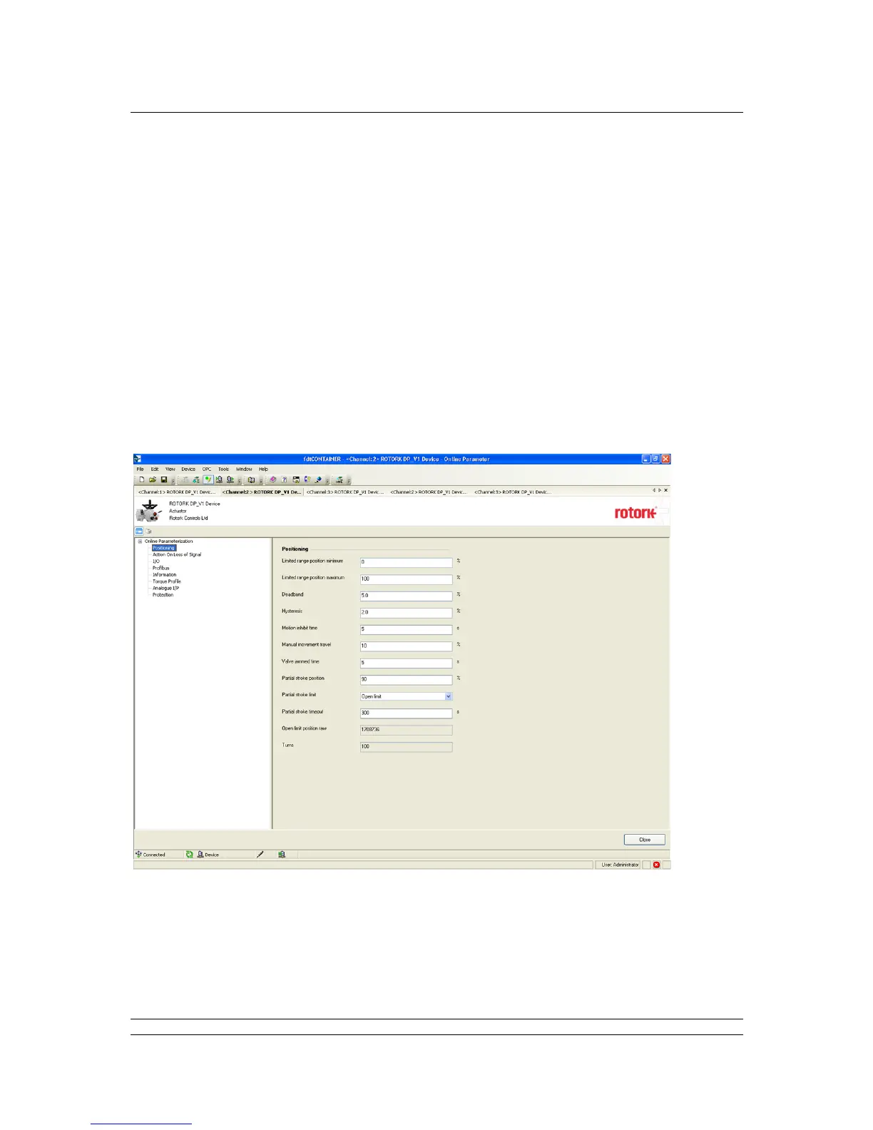
This utility uses DTM device description files and a suitable FDT container. A typical configuration
screen is illustrated below.
The settings for the parameters and the control and review of actuator information can all be carried
out in the FDT container using the DTM. The screens displayed will be dependent on the software
version of the profibus card and the actuator type.