5 THE ACTUATOR CYCLIC DATA SIGNALS
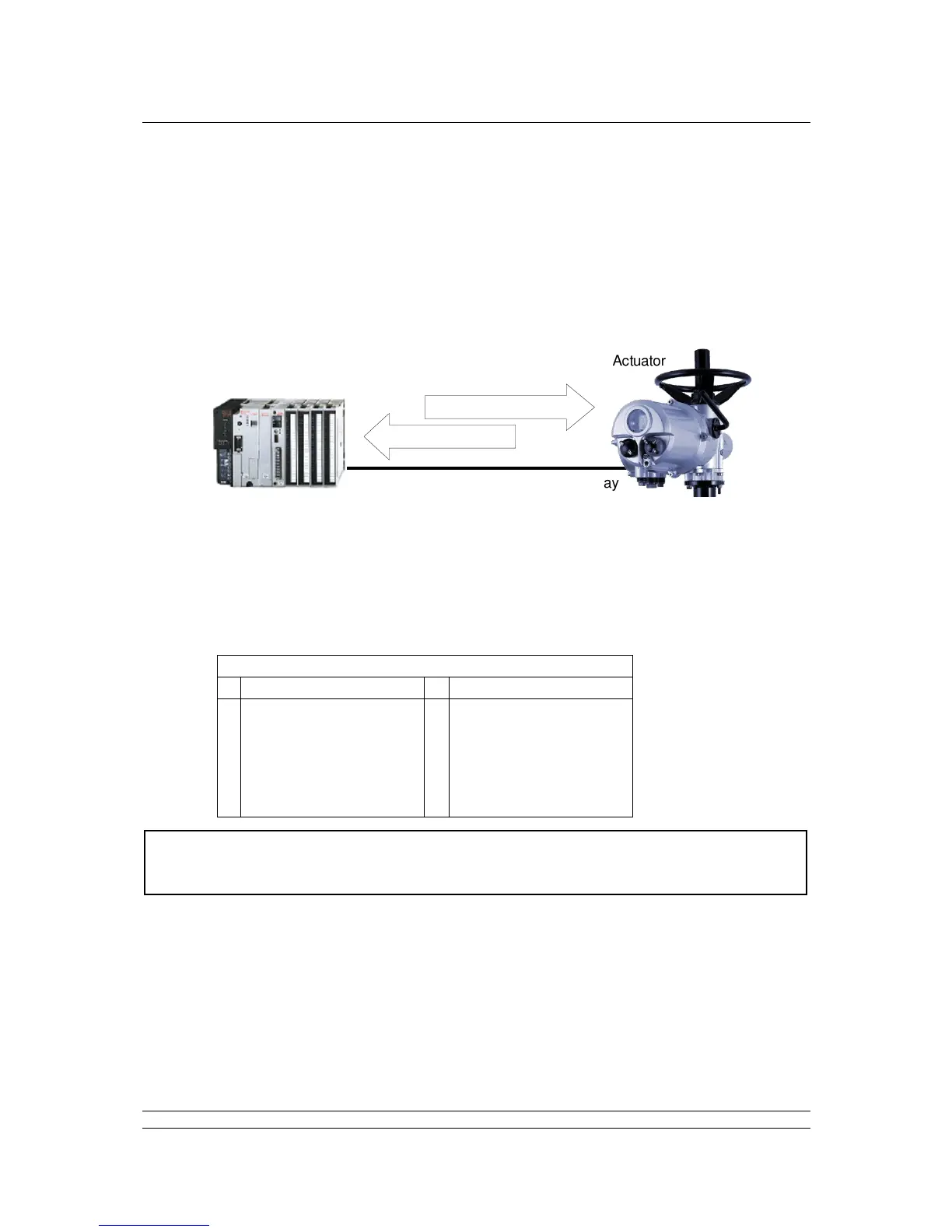
The Profibus DP Module (Mk2) allows the actuator to be controlled by, and to report data to, a suitable
host device using Profibus DP protocol. This section explains the data signals that are presented
during cyclic V0 data exchange and their meaning in relation to the actuator functionality. The register
locations used for the data exchange are given later in this manual.
This section also gives information on the other control inputs available for moving the actuator.
Outputs are defined as signals originating at the PLC and operating the actuator
controls.
Inputs are defined as signals originating at the actuator and fed back to the PLC over the
Profibus network.
Note: The actual registers exchanged during normal cyclic data exchange will depend on
the Configuration set for the card. Section 5.4 contains information on the
Configuration options available.