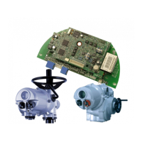
Profibus DP Mk2 Option Card Installation Manual
60 of 84 Publication PUB088-005-00_1017
0 – 255 sec
0000 – 00FF hex
0 = Nothing (No Action)
1 = Open
3 = Close
5 = Stop
7 = Position
Any other value = Off
0 – 255 sec
0000 – 00FF hex
ESD DI4/Net Disable
and Data logger disable
DI-4 is ESD = 0 or 2
DI-4 is Net Disable = 1 or 3
Data Logger is enabled = 0 or 1
Data Logger is disabled = 2 or 4
(Bit 0 = EDS/Net disable
Bit 1 = data logger en/disable)
ESD and
Data Logger
enabled
0
0000 hex
Redundancy FR/SR mode
and Simple/RedCom mode
Bit 0 : SR mode = 0, FR mode = 1
Bit 1 : Simple = 0, RedCom = 1
Part Stroke Limit and timeout
Bit 15 is 0 for close limit and 1 for open
limit.
Bits 0-14 are time values in seconds for
timeout
Open and
300 secs
812C hex
0–Don’t know (default), 2–A/AQ/Q,
6–IQ, 8–IQT, 9–EH, 10–Skilmatic,
11–Multiport, 12-CVAL, 13-CVAQ,
14- ROMPAK
Note: - Setting the
deadband lower than the hysteresis, or the hysteresis greater than the
deadband causes the hysteresis to be set to 0.1%
- IQ Setting tool only allows 0.0 to 9.9% deadband to be set
- On Redcom Dual Channel cards the default is 2 (0002 hex)
These parameters set up the response the actuator will make to various control and network actions.
There are three GSD files, one for a single channel card, one for a simple dual channel and one for a
RedCom dual channel card. They all contain the same number of parameter settings.
Single Channel Card GSD file RTRK0845
Simple Dual Channel Card GSD file RTRC0845
RedCom Dual Channel Card GSD file RTRR0845