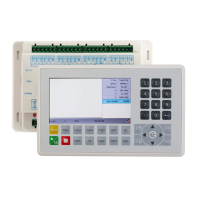
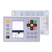
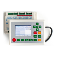
RDC6445G/S Control System manual
SHENZHEN RUIDA TECHNOLOGY
Directional signal (OC output)
5V Power positive (output)
The polarity of directional signal for driver pulse signal can be set. Where a certain axle is
reset, it will move to the opposite direction of machine origin, which means the polarity of
directional signal for this axle is not correct. In such a case, the connection between this axle and
the motor driver can be broken first (otherwise the mainboard can not be detected to the spacing
so as to lead to the collision of this axle), and then such a polarity can be corrected after this axle
is reset completely. Upon the correction, the reset key can be pressed against to reset the
And, the Pulse signal can be falling edge valid or rising edge valid. The default setting is
The Pulse signal and the directional signal are all OC outputs. The
Controller must be common anode with the motor driver
4.10 Laser Power Control Interface CN5/CN6
This control system has two independent and adjustable digital laser power control
interfaces. Signals of the two interfaces are similar and the first digital interface (CN5) is hereby
Laser-enabled control interface
1. When the laser is the RF laser, this pin will not be used;
2. When the laser is a glass tube, if the used laser is outputted in
the low-level form, this pin will be connected with the laser power
enable end and used to control the ON/Off of laser.
Power control interface of laser/laser tube
1. When the laser is the RF laser, this pin will be connected with
the laser RF-PWM end;
2. When the laser is a glass tube, this pin will be connected with
the laser power PWM end and used to control the power of the
laser.
The input port of water protector for the first laser power source.
When the water protector 1 is enabled, the mainboard will detect