Chapter 1 Operation Procedures
Operation Edition - 54
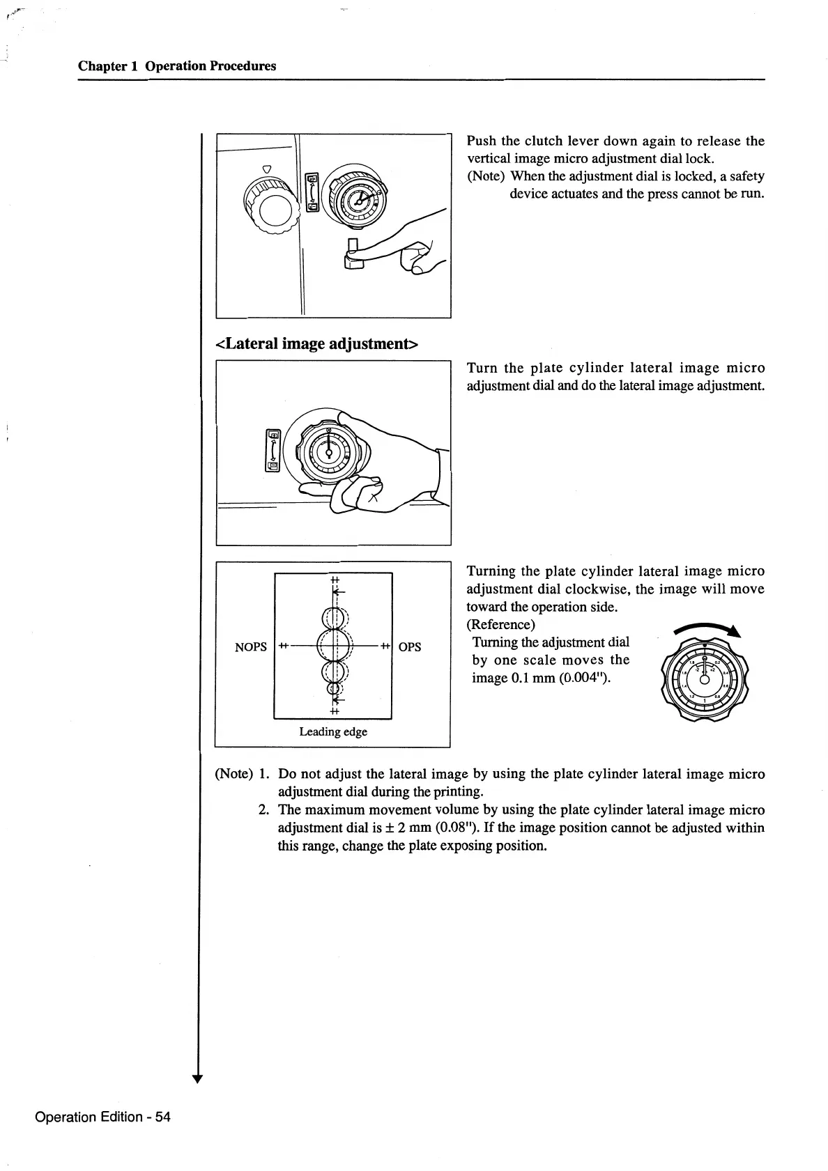
<Lateral image adjustment>
Leading edge
Push the clutch lever down again to release the
vertical image micro adjustment dial lock.
(Note) When the adjustment dial
is
locked, a safety
device actuates and the press cannot be run.
Turn
the
plate
cylinder
lateral
image
micro
adjustment dial and do the lateral image adjustment.
Turning the plate cylinder lateral image
micro
adjustment dial clockwise, the image will move
toward the operation side.
(Reference)
r
.....
Turning the adjustment dial
by
one
scale
moves the
image
0.1
mm (0.004").
(Note)
1.
Do not adjust the lateral image by using the plate cylinder lateral image micro
adjustment dial during the printing.
2.
The maximum movement volume by using the plate cylinder lateral image micro
adjustment dial
is±
2 mm (0.08").
If
the image position cannot be adjusted within
this range, change the plate exposing position.
 Loading...