• Testing Drive Motor Controller
• Testing Steps: (resistance of output)
1. Set DMM to Resistance
2. Test for continuity between any two terminals
3. Test for continuity between other terminals
4. Measurements should be nearly identical
a. Typical resistance should be ~18.5K
• Testing Steps: (power and ground to output)
1. Set DMM to Diode
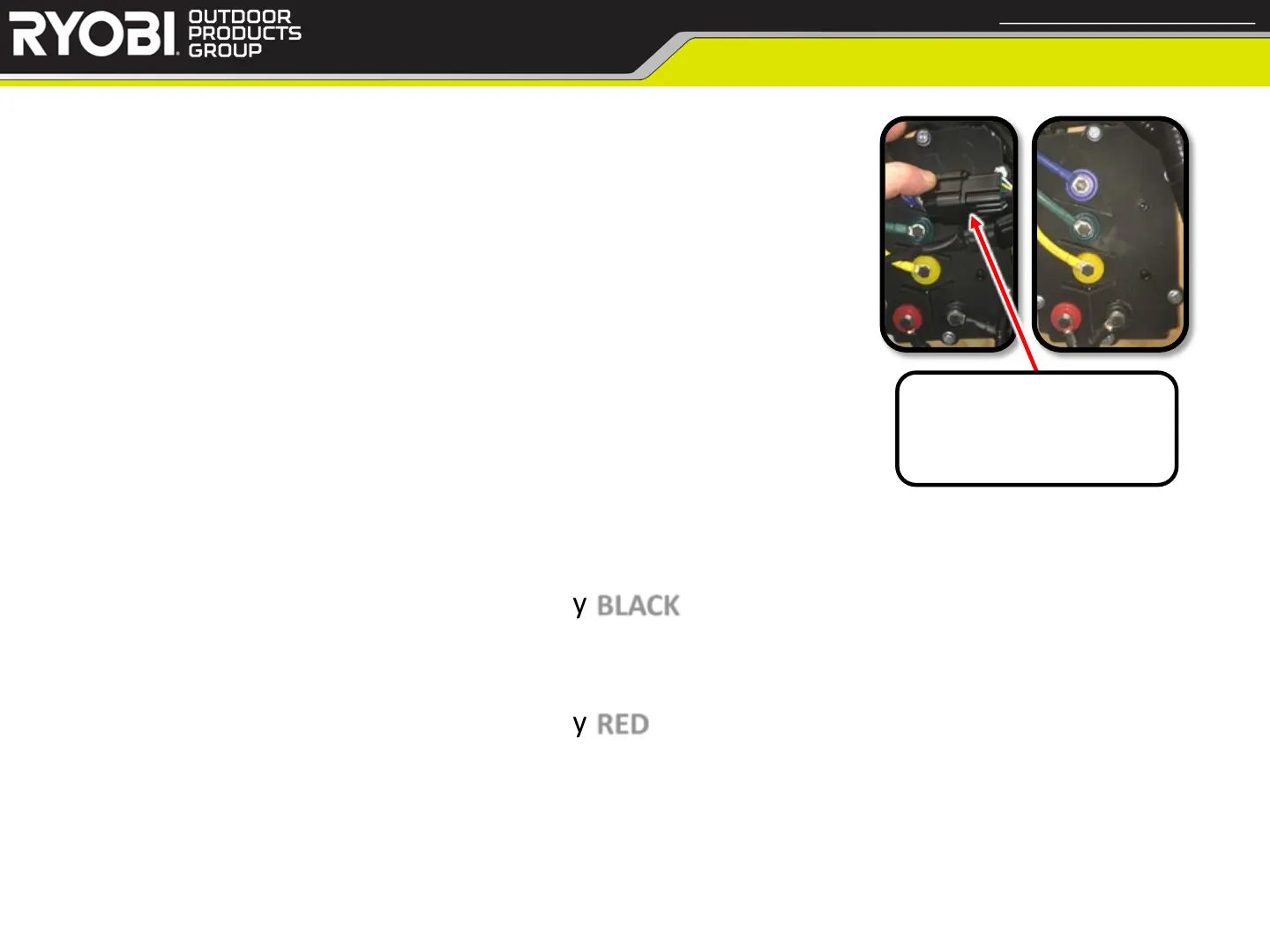
2. Connect black lead of DMM to heavy BLACK wire
3. Sequentially connect the red probe to each heavy phase wire
a. Measurement should be OL or OPEN for each heavy phase wire
4. Connect black lead of DMM to heavy RED wire
5. Sequentially connect the red probe to each heavy phase wire
a. Measurement should be ~0.45v for each heavy phase wire
40
< Return to Table of Contents
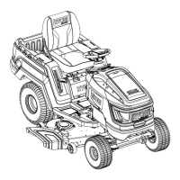
Drive Motor Controllers
Confidential and Proprietary - Property of Techtronic Power Equipment - DO NOT COPY or DISCLOSE
Primary Deck Motor
Controller has the large
square connector.