• Testing Brake Switch
• Testing Steps:
1. Set DMM to DC Volts
2. Disconnect Brake Switch connector
3. Measure between RED & BLACK terminals on
mating connector of the harness
a. Nominal voltage should be 3.2v when plunger
depressed and 0v when plunger released
42
< Return to Table of Contents
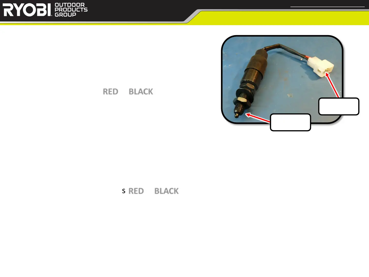
Brake Switch
Confidential and Proprietary - Property of Techtronic Power Equipment - DO NOT COPY or DISCLOSE
Contacts
Plunger
• Testing Steps: (testing independently)
1. Power mower off
2. Set DMM to Resistance
3. Disconnect Brake Switch connector
4. Test for continuity across RED & BLACK contacts
a. With the plunger released, you should get very low resistance or Continuity
b. With the plunger depressed, you should get very high resistance or no Continuity