48
< Return to Table of Contents
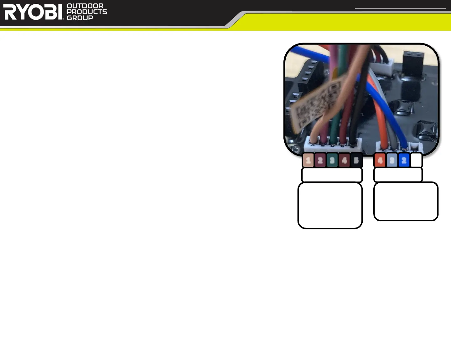
Mixing Board
Confidential and Proprietary - Property of Techtronic Power Equipment - DO NOT COPY or DISCLOSE
1 2
3
4
5
4 3 2 1
LEFT (L)
RIGHT (R)
1: Joystick X
2: Joystick Y
3: Neutral Switch
4: Mix. Board 5v
5: Mix. Board GND
4: Right Drive GND
3: Right Drive 5v
2: Right Drive Signal
1: Unused
• Testing Mixing Board (continued)
• Testing Steps:
8. Test right wheel Drive Motor Controller
a. Set Joystick to neutral position
b. Place black DMM lead onto socket R4 (Right Drive
Ground)
c. Place red DMM lead onto socket R2 (Right Drive Signal)
1. Voltage should measure ~2.4v; replace if necessary
d. Pull Joystick out of neutral position
e. Move Joystick forward to backward
1. Sweeping voltage should measure 1.5v-4.8v; replace if necessary