Chapter 4: Operation
Firmware – S2011 and S3012
Revision: 1 (9/98) 29 © Saftronics, Inc.
Table 10 Typical Operation by Digital Operator (continued)
¯ Frequency Reference Value Change
(15 Hz to 60 Hz)
Fref
• Select frequency reference value
display.
Press 7 times
15.0
• Change set value.
Change the value
by pressing
\ /
60.0
Fref
/ \
• Write-in set value.
60.0
Fref
• Select output frequency monitor display.
60.0
Fref
°
Reverse Run
• Select reverse run.
fo
F/R
Press 3 times
Switch to “rev”
\ /
by pressing
eu
F/R
/ \
• Write-in set value.
eu
F/R
• Select output frequency monitor display.
60.0
Fout
Press 5 times
±
Stop
• Decelerates to a stop.
0.0
Fout
RUN LED OFF STOP LED ON
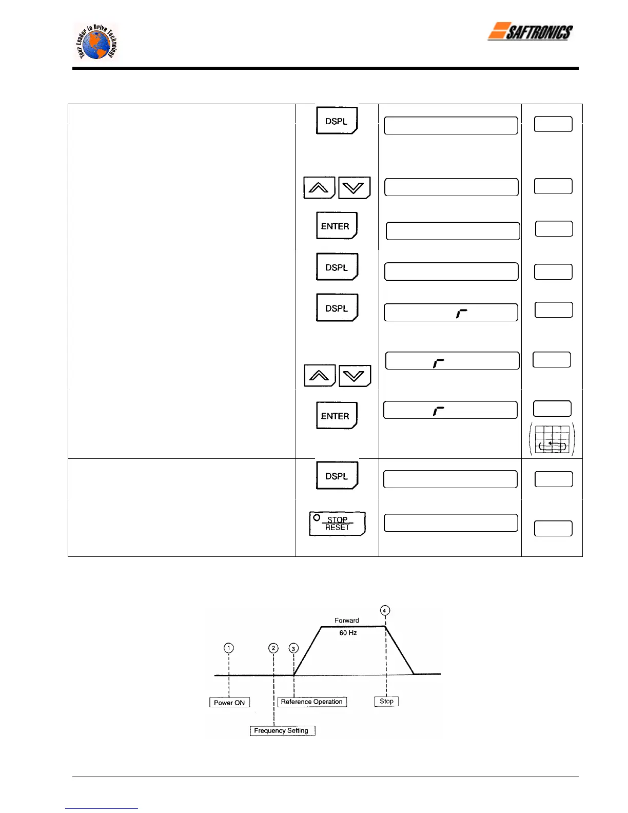
§ Operation by Control Circuit Terminal Signal
The diagram below shows a typical operation pattern using the control circuit terminal signals.
Figure 16 Operation Sequence by Control Circuit Terminal Signal
efesotomasyon.com - Control Techniques,emerson,saftronics -ac drive-servo motor